Sony BKM-21D Installation Manual - Page 30
Specifications
 |
View all Sony BKM-21D manuals
Add to My Manuals
Save this manual to your list of manuals |
Page 30 highlights
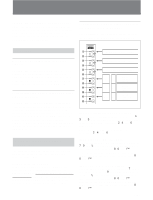
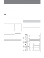
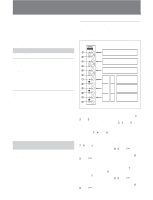
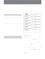
BKM-21D SDI Multi Decoder Adaptor Input of serial digital signals You can input serial digital signals to connectors 1, 3, and 5. You can obtain active loop-through output of those signals from connectors 2, 4, and 6, respectively. You need not attach 75-ohm terminations to connectors 2, 4, and 6. Input of analog composite signals You can input analog composite signals to connectors 7, 9, and !¡. You can obtain loop-through output of those signals from connectors 8, 0, and !™ , respectively. If you do not wish to use loop-through output, attach 75-ohm terminators to connectors 8, 0, and !™ . Input of Y/R-Y/B-Y or RGB signals You can input a Y or G signal to connector 7, an B-Y or B signal to connector 9, and a R-Y or R signal to connector !¡. You can obtain loop-through output of those signals from connectors 8, 0, and !™ , respectively. If you do not wish to use loop-through output, attach 75-ohm terminators to connectors 8, 0, and !™ . Assigning Input Signals to Connectors Before inputting signals to the BKM-21D, you must specify the type and format of the signal that will be input to each connector. To assign input signals to each connector, use the on-screen INPUT CONFIGURATION menu of your video monitor. For information about using the INPUT CONFIGURATION menu, refer to the manual of your video monitor. Specifications General Power requirements +5 V, ±6 V, -15 V (supplied from the monitor) Power consumption 11 W Recommended operating temperature 20°C to 30°C (68°F to 86°F) Permissible operating temperature 0°C to 40°C (32°F to 104°F) 6(E) Operating humidity 0% to 90% (no condensation) Maximum external dimensions (w/h/d) 25 × 256 × 245 mm (31/32 × 101/8 × 93/4 inches) Mass 770g (1 lb 11oz) Input/Output Connectors Digital input Analog input BNC × 3, with active loopthrough output BNC × 3, high impedance, with loop-through output Signal Characteristics Analog composite signals Signal level 1 Vp-p +3 dB/-6 dB Luminance signal Frequency characteristics Filter off: 100 Hz to 5 MHz ±1 dB (monochrome signal) Filter on: -30 dB relative to subcarrier frequency Chrominance signals Demodulation axis NTSC, PAL: R-Y/B-Y Chrominance signal band (R-Y, B-Y) NTSC COMB filter: 0.9 MHz-3dB TRAP/BPF filter: 0.7 MHz-3dB PAL COMB filter: 1.1 MHz-3dB TRAP/BPF filter: 0.9 MHz-3dB Subcarrier reproduction error ±1% max. Subcarrier synchronization range ±150 Hz min. Chroma phase adjustment range NTSC: ±15° min. PAL: ±10° min. DG (differential gain) APL 10% to 90% 2% max. DP (differential phase) APL 10% to 90% 2° max. Chrominance signal/luminance signal Delay error 35 nsec max. Gain error 5% max.
-
 1
1 -
2
-
3
-
4
-
5
-
6
-
7
-
8
-
9
-
10
-
11
-
12
-
13
-
14
-
15
-
16
-
17
-
18
-
19
-
20
-
21
-
22
-
23
-
24
-
 25
25 -
 26
26 -
 27
27 -
 28
28 -
 29
29 -
 30
30 -
 31
31 -
 32
32 -
 33
33 -
 34
34 -
 35
35 -
36
-
37
-
38
-
39
-
40
-
41
-
42
-
43
-
44
-
45
-
46
-
47
-
48
 |
 |
