Sony CDX-CA700X Installation/Connection Instructions - Page 2
Beim Einbau dieses Ger - manual
 |
View all Sony CDX-CA700X manuals
Add to My Manuals
Save this manual to your list of manuals |
Page 2 highlights
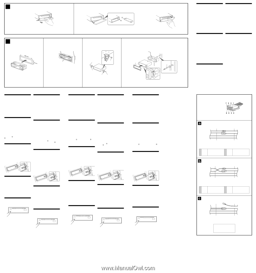
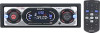
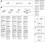
4A 51 1 B c 1 2 2 Bend these claws outward for a tight fit, if necessary. Falls erforderlich, diese Klammern für einen sicheren Halt hochbiegen. Pliez ces griffes vers l'extérieur pour assurer une prise correcte si nécessaire. Piegare questi morsetti per un'installazione più sicura, se necessario. Indien nodig kunt u deze lipjes ombuigen voor een steviger bevestiging. 3 5 5 7 7 7 5 4 Dashboard Armaturenbrett Tableau de bord Cruscotto Dashboard 1 4 Fire wall Motorraumtrennwand Paroi ignifuge Parete tagliafiamma Brandschot 2 3 Precautions • Choose the installation location carefully so that the unit will not interfere with normal driving operations. • Avoid installing the unit in areas subject to dust, dirt, excessive vibration, or high temperature, such as in direct sunlight or near heater ducts. • Use only the supplied mounting hardware for a safe and secure installation. Mounting angle adjustment Adjust the mounting angle to less than 60°. How to detach and attach the front panel (4) Before installing the unit, detach the front panel. 4-A To detach Before detaching the front panel, be sure to press (OFF). Press (OPEN), then slide the front panel to the right side, and pull out the left side. 4-B To attach Place the hole in the front panel onto the spindle on the unit as illustrated, then push the left side in. Mounting example (5) Installation in the dashboard Note When installing this unit: Depending on car type, the mounting angle may not allow the front panel to open easily. In such a case, remove the silver screw A shown below. When screwing it on again, first lock the lever B. Attaching the screw without doing so may cause the unit to break. B A Vorsichtsmaßnahmen • Wählen Sie den Einbauort sorgfältig so aus, dass das Gerät beim Fahren nicht hinderlich ist. • Bauen Sie das Gerät so ein, dass es keinen hohen Temperaturen (keinem direkten Sonnenlicht, keiner Warmluft von der Heizung), keinem Staub, keinem Schmutz und keinen starken Vibrationen ausgesetzt ist. • Für eine sichere Befestigung verwenden Sie stets nur die mitgelieferten Montageteile. Hinweis zum Montagewinkel Das Gerät sollte in einem Winkel von weniger als 60° montiert werden. Abnehmen und Anbringen der Frontplatte (4) Nehmen Sie die Frontplatte vor dem Einbau des Geräts ab. 4-A Abnehmen Drücken Sie auf jeden Fall (OFF), bevor Sie die Frontplatte abnehmen. Drücken Sie (OPEN), schieben Sie dann die Frontplatte nach rechts und ziehen Sie sie an der linken Seite heraus. 4-B Anbringen Setzen Sie die Aussparung an der Frontplatte wie in der Abbildung dargestellt am Stift am Gerät an und drücken Sie dann die linke Seite hinein. Montagebeispiel (5) Installation im Armaturenbrett Hinweis Beim Einbau dieses Geräts: Je nach Fahrzeugtyp lässt sich die Frontplatte aufgrund des Montagewinkels möglicherweise nicht problemlos öffnen. Entfernen Sie in einem solchen Fall die silberne Schraube A (siehe unten). Wenn Sie die Schraube wieder anbringen, arretieren Sie zuerst den Hebel B. Wenn Sie die Schraube anbringen, ohne den Hebel zu arretieren, kann das Gerät beschädigt werden. Warning when installing in a car without ACC (accessory) position on the ignition key switch Be sure to press (OFF) on the unit for two seconds to turn off the clock display after turning off the engine. When you press (OFF) only momentarily, the clock display does not turn off and this causes battery wear. RESET button When the installation and connections are completed, be sure to press the RESET button with a ballpoint pen, etc. B A Warnhinweis zur Installation des Geräts in einem Auto mit Zündschloss ohne Zubehörposition ACC oder I Drücken Sie am Gerät unbedingt zwei Sekunden lang (OFF), um die Uhrzeitanzeige auszuschalten, nachdem Sie den Motor ausgeschaltet haben. Wenn Sie (OFF) nur kurz drücken, wird die Uhrzeitanzeige nicht ausgeschaltet und der Autobatterie wird Strom entzogen. Taste RESET Nach der Installation und dem Anschluss muss die Taste RESET mit einem Kugelschreiber o. ä. gedrückt werden. Précautions • Choisissez soigneusement l'emplacement de l'installation afin que l'appareil ne gêne pas la conduite normale du véhicule. • Evitez d'installer l'appareil dans un endroit exposé à la poussière, à la saleté, à des vibrations excessives ou à des températures élevées comme en plein soleil ou à proximité de conduits de chauffage. • Pour garantir un montage sûr, n'utilisez que le matériel fourni. Réglage de l'angle de montage Ajustez l'inclinaison à un angle inférieur à 60°. Precauzioni • Scegliere con attenzione la posizione per l'installazione in modo che l'apparecchio non interferisca con le operazioni di guida del conducente. • Evitare di installare l'apparecchio dove sia soggetto ad alte temperature, come alla luce solare diretta o al getto di aria calda dell'impianto di riscaldamento, o dove possa essere soggetto a polvere, sporco e vibrazioni eccessive. • Usare solo il materiale di montaggio in dotazione per un'installazione stabile e sicura. Regolazione dell'angolo di montaggio Regolare l'angolo di montaggio in modo che sia inferiore a 60°. Retrait et pose de la façade (4) Avant d'installer l'appareil, retirez la façade. 4-A Pour retirer Avant de retirer la façade, n'oubliez pas d'appuyer d'abord sur (OFF). Appuyez sur (OPEN), puis faites glisser la façade vers la droite et retirez-la par la gauche. 4-B Pour poser Fixez la partie de la façade sur la partie de l'appareil, comme indiqué sur l'illustration, puis appuyez sur le côté gauche. Exemple de montage (5) Installation dans le tableau de bord Remarque Lors de l'installation de cet appareil : suivant le type de voiture, il se peut que l'angle de montage complique l'ouverture du panneau frontal. En pareil cas, retirez la vis argentée A indiquée ci-dessous. Pour la revisser, verrouillez d'abord le levier B. Si vous installez la vis sans verrouiller le levier, vous risquez de casser l'appareil. B Come rimuovere e reinserire il pannello anteriore (4) Prima di installare l'apparecchio rimuovere il pannello anteriore. 4-A Per rimuoverlo Prima di rimuovere il pannello anteriore, assicurarsi di premere (OFF). Premere (OPEN), quindi far scivolare il pannello anteriore verso destra e tirare il lato sinistro verso di sé. 4-B Per reinserirlo Applicare il foro del pannello anteriore al mandrino dell'apparecchio come mostrato nell'illustrazione e premere il lato sinistro fino a sentire uno scatto. Esempio di montaggio (5) Installazione nel cruscotto Nota Installazione dell'apparecchio: a seconda del tipo di macchina l'angolo di montaggio potrebbe impedire al pannello frontale di aprirsi facilmente. In tal caso, rimuovere la vite argentata A indicata in basso. Quando si riapplica la vite, bloccare prima la leva B, altrimenti l'apparecchio potrebbe rompersi. A B A Avertissement en cas d'installation dans une voiture dont le contact ne comporte pas de position ACC (accessoires) Appuyez sur la touche (OFF) de l'appareil pendant deux secondes pour désactiver l'affichage de l'horloge après avoir coupé le moteur. Si vous n'appuyez que brièvement sur (OFF), l'affichage de l'horloge ne disparaît pas, ce qui provoque la décharge de la batterie. Touche RESET Quand l'installation et les raccordements sont terminés, appuyez sur la touche RESET avec un stylo à bille, etc. Informazioni importanti per quando si effettua l'installazione su un'auto sprovvista della posizione ACC sull'interruttore di accensione Assicurarsi di premere (OFF) sull'apparecchio per due secondi per spegnere il display dell'orologio dopo che il motore è stato spento. Se si preme (OFF) solo per un attimo, il display dell'orologio non si spegne causando in questo modo lo scaricamento della batteria. Tasto RESET Dopo avere terminato l'installazione e i collegamenti, assicurarsi di premere il tasto RESET con la punta di una penna a sfera, ecc. Voorzorgsmaatregelen • Kies de installatieplaats zorgvuldig zodat het toestel de bestuurder niet hindert tijdens het rijden. • Installeer het apparaat niet op plaatsen waar het blootgesteld wordt aan hoge temperaturen, b.v. in direct zonlicht of bij de warme luchtstroom van de autoverwarming, aan sterke trillingen, of waar het in contact komt met veel stof of vuil. • Gebruik voor het veilig en stevig monteren van het apparaat uitsluitend de bijgeleverde montageonderdelen. Maximale montagehoek Installeer het apparaat nooit onder een hoek van meer dan 60° met het horizontale vlak. Verwijderen en bevestigen van het afneembare voorpaneel (4) Verwijder, alvorens met het installeren te beginnen, het afneembare voorpaneel. 4-A Verwijderen Druk eerst op (OFF) alvorens het voorpaneel los te maken. Druk op (OPEN), schuif het voorpaneel naar rechts en trek het los aan de linkerkant. 4-B Bevestigen Breng deel van het voorpaneel aan op deel van het apparaat zoals afgebeeld en druk op de linkerzijde tot deze vastklikt. Montagevoorbeeld (5) Montage in het dashboard Opmerking Installatie van het toestel: Afhankelijk van het automodel kan de montagehoek het openen van het frontpaneel belemmeren. Verwijder dan de zilverkleurige schroef A zoals hieronder getoond. Wanneer u de schroef opnieuw wilt vastschroeven, moet u eerst hendel B blokkeren. Zoniet kunt u het toestel beschadigen. B A Opgelet bij het monteren in een auto waarvan het contactslot geen ACC (accessory) stand heeft Druk (OFF) op het toestel gedurende twee seconden in om de klokweergave uit te schakelen na het afzetten van de motor. Indien u slechts even op (OFF) drukt, verdwijnt de tijdindicatie niet waardoor de batterij uitgeput raakt. RESET-toets Druk, nadat u het apparaat heeft geïnstalleerd en de aansluitingen heeft gemaakt, met een balpen of een ander puntig voorwerp op de RESET-toets. Power connection diagram Auxiliary power connector may vary depending on the car. Check your car's auxiliary power connector diagram to make sure the connections match correctly. There are three basic types (illustrated below). You may need to switch the positions of the red and yellow leads in the car stereo's power connecting cord. After matching the connections and switched power supply leads correctly, connect the unit to the car's power supply. If you have any questions and problems connecting your unit that are not covered in this manual, please consult the car dealer. Diagramma dei collegamenti di alimentazione Il connettore di alimentazione ausiliaria può variare a seconda della macchina. Controllare il diagramma del connettore di alimentazione ausiliaria della macchina per essere sicuri che le connessioni corrispondano correttamente. Vi sono tre tipi di base (illustrazione sotto). Potrà essere necessario cambiare le posizioni dei conduttori rosso e giallo nel cavo di alimentazione dello stereo della macchina. Dopo aver fatto corrispondere le connessioni e i cavi di alimentazione commutata, collegare l'apparecchio all'alimentazione della macchina. Se si hanno domande o se sorgono problemi che non sono stati trattati nel manuale nel collegare l'apparecchio, contattare l'autoconcessionario. Anschlussdiagramm Der Hilfsstromanschluss kann je nach Fahrzeugtyp unterschiedlich sein. Sehen Sie im Hilfsstromanschlussdiagramm für Ihr Fahrzeug nach, wie die Verbindung ordnungsgemäß vorgenommen werden muss. Es gibt, wie unten abgebildet, drei grundlegende Typen. Sie müssen möglicherweise die rote und gelbe Leitung des Stromversorgungskabels der Autostereoanlage vertauschen. Stellen Sie die Anschlüsse her, schließen Sie die geschalteten Stromversorgungsleitungen richtig an und verbinden Sie dann das Gerät mit der Stromversorgung Ihres Fahrzeugs. Wenn beim Anschließen des Geräts Fragen oder Probleme auftreten, die in dieser Bedienungsanleitung nicht erläutert werden, wenden Sie sich bitte an den Autohändler. Voedingsaansluitschema De hulpvoedingsaansluiting kan verschillen naargelang van de wagen. Controleer het voedingsaansluitschema dat bij dit toestel wordt geleverd om te zien of de aansluitingen kloppen. Er zijn drie basistypes (zie illustratie hieronder). Het is mogelijk dat u de posities van de rode en gele kabels in het aansluitsnoer van het car audiosysteem moet omwisselen. Als de aansluitingen en geschakelde voedingskabels kloppen, sluit u het toestel aan op de voeding van de wagen. Indien u nog vragen of problemen hebt in verband met het aansluiten van het toestel die niet in deze handleiding vermeld staan, raadpleeg dan de autodealer. Schéma de connexion d'alimentation Le connecteur d'alimentation auxiliaire peut varier suivant le type de voiture. Vérifiez le schéma du connecteur d'alimentation auxiliaire de votre voiture pour vous assurer que les connexions correspondent. Il en existe trois types de base (illustrés ci-dessous). Il se peut que vous deviez commuter la position du fil rouge et jaune du cordon d'alimentation de l'autoradio. Après avoir établi les connexions et commuté correctement les fils d'alimentation, raccordez l'appareil à l'alimentation de la voiture. Si vous avez des questions ou des difficultés à propos de la connexion de cet appareil qui ne sont pas abordées dans le présent mode d'emploi, consultez votre revendeur automobile. Auxiliary power connector Hilfsstromanschluss Connecteur d'alimentation auxiliaire Connettore di alimentazione ausiliare Hulpvoedingsaansluiting Red Rot Rouge Rosso Rood Red Rot Rouge Rosso Rood Yellow Gelb Jaune Giallo Geel Yellow Gelb Jaune Giallo Geel Yellow continuous power supply Red Gelb permanente Stromversorgung Rot 4 Jaune alimentation continue 7 Rouge Giallo alimentazione continua Rosso Geel continu voeding Rood switched power supply geschaltete Stromversorgung alimentation commutée alimentazione commutata geschakelde voeding Red Rot Rouge Rosso Rood Red Rot Rouge Rosso Rood Yellow Gelb Jaune Giallo Geel Yellow Gelb Jaune Giallo Geel Yellow Gelb 4 Jaune Giallo Geel switched power supply geschaltete Stromversorgung alimentation commutée 7 alimentazione commutata geschakelde voeding Red Rot Rouge Rosso Rood continuous power supply permanente Stromversorgung alimentation continue alimentazione continua continu voeding Red Rot Rouge Rosso Rood Red Rot Rouge Rosso Rood Yellow Gelb Jaune Giallo Geel Yellow Gelb Jaune Giallo Geel the car without ACC position Fahrzeug ohne Zubehörposition ACC Voiture sans position ACC la macchina senza posizione ACC Wagen zonder ACC stand
-
 1
1 -
 2
2
 |
 |