Sony DCRDVD610 Operating Guide - Page 130
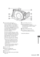
Identifying parts and controls Continued, An Active Interface Shoe
 |
UPC - 027242727700
View all Sony DCRDVD610 manuals
Add to My Manuals
Save this manual to your list of manuals |
Page 130 highlights
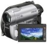
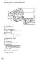
Identifying parts and controls (Continued) A POWER switch (25) B Viewfinder (27) C CHG (charge) lamp (21) D (Movie)/ (Still) mode lamps (25) E Battery pack (21) F Built-in microphone (40) An Active Interface Shoe* compatible microphone (optional) will take precedence when connected. G Power zoom lever (40, 46) H PHOTO button (34, 39) I DC IN jack (21) J START/STOP button (34, 39) K Tripod receptacle Attach the tripod (optional: the length of the screw must be less than 5.5 mm (7/32 in.)) to the tripod receptacle using a tripod screw. L BATT (battery) release lever (22) * DCR-DVD710/DVD810 130
-
 1
1 -
2
-
3
-
4
-
5
-
6
-
7
-
8
-
9
-
10
-
11
-
12
-
13
-
14
-
15
-
16
-
17
-
18
-
19
-
20
-
21
-
22
-
23
-
24
-
25
-
26
-
27
-
28
-
29
-
30
-
31
-
32
-
33
-
34
-
35
-
36
-
37
-
38
-
39
-
40
-
41
-
42
-
43
-
44
-
45
-
46
-
47
-
48
-
49
-
50
-
51
-
52
-
53
-
54
-
55
-
56
-
57
-
58
-
59
-
60
-
61
-
62
-
63
-
64
-
65
-
66
-
67
-
68
-
69
-
70
-
71
-
72
-
73
-
74
-
75
-
76
-
77
-
78
-
79
-
80
-
81
-
82
-
83
-
84
-
85
-
86
-
87
-
88
-
89
-
90
-
91
-
92
-
93
-
94
-
95
-
96
-
97
-
98
-
99
-
100
-
101
-
102
-
103
-
104
-
105
-
106
-
107
-
108
-
109
-
110
-
111
-
112
-
113
-
114
-
115
-
116
-
117
-
118
-
119
-
120
-
121
-
122
-
123
-
124
-
 125
125 -
 126
126 -
 127
127 -
 128
128 -
 129
129 -
 130
130 -
 131
131 -
 132
132 -
 133
133 -
 134
134 -
 135
135 -
136
-
137
-
138
-
139
-
140
-
141
-
142
-
143
-
144
-
145
-
146
-
147
-
148
-
149
-
150
-
151
-
152
-
153
-
154
-
155
-
156
-
157
-
158
-
159
 |
 |

130
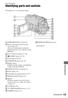
Identifying parts and controls (Continued)
A
POWER switch (25)
B
Viewfinder (27)
C
CHG (charge) lamp (21)
D
(Movie)/
(Still) mode lamps (25)
E
Battery pack (21)
F
Built-in microphone (40)
An Active Interface Shoe
*
compatible
microphone (optional) will take
precedence when connected.
G
Power zoom lever (40, 46)
H
PHOTO button (34, 39)
I
DC IN jack (21)
J
START/STOP button (34, 39)
K
Tripod receptacle
Attach the tripod (optional: the length of
the screw must be less than 5.5 mm
(7/32 in.)) to the tripod receptacle using
a tripod screw.
L
BATT (battery) release lever (22)
*
DCR-DVD710/DVD810