Sony DR-BT22 Operating Instructions - Page 7
Location and Function of Parts - ear pads
 |
UPC - 027242712690
View all Sony DR-BT22 manuals
Add to My Manuals
Save this manual to your list of manuals |
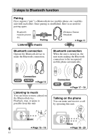
Page 7 highlights
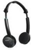
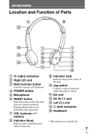
GETTING STARTED Location and Function of Parts qg qf L 7 qd 8 9 qs 0 qa R 1 2 3 4 5 6 1 R (right) indication 2 Right (R) unit 3 Multi function button Controls various call functions. 4 POWER button 9 Indicator (red) Indicates the power status of the unit. 0 Jog switch Controls various functions when listening to music. 5 Microphone qa Ear pad 6 RESET button Push this button when this unit does not operate properly. Pairing information is not deleted by this operation. 7 VOL (volume) +*⁄- buttons qs DC IN 3 V jack qd Left (L) unit qf L (left) indication qg Headband 8 Indicator (blue) Indicates the communication * This button has a tactile dot. status of the unit. 7 US
-
 1
1 -
 2
2 -
 3
3 -
 4
4 -
 5
5 -
 6
6 -
 7
7 -
 8
8 -
 9
9 -
 10
10 -
 11
11 -
 12
12 -
13
-
14
-
15
-
16
-
17
-
18
-
19
-
20
-
21
-
22
-
23
-
24
-
25
-
26
-
27
-
28
-
29
-
30
-
31
-
32
-
33
-
34
-
35
-
36
-
37
-
38
-
39
-
40
-
41
-
42
-
43
-
44
-
45
-
46
-
47
-
48
-
49
-
50
-
51
-
52
-
53
-
54
-
55
-
56
 |
 |

7
US
Location and Function of Parts
1
R
(right) indication
2
Right (
R
) unit
3
Multi function button
Controls various call functions.
4
POWER button
5
Microphone
6
RESET button
Push this button when this unit
does not operate properly.
Pairing information is not
deleted by this operation.
7
VOL (volume) +
*
/–
buttons
8
Indicator (blue)
Indicates the communication
status of the unit.
9
Indicator (red)
Indicates the power status of
the unit.
0
Jog switch
Controls various functions
when listening to music.
qa
Ear pad
qs
DC IN 3 V jack
qd
Left (
L
) unit
qf
L
(left) indication
qg
Headband
GETTING STARTED
* This button has a tactile dot.
R
L
qg
qf
qd
qs
qa
0
9
8
7
1
2
3
4
5
6