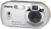
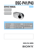
Sony DSC-P41 Service Manual - Page 4
TABLE OF CONTENTS, Discharging of the ST-098 Board's Charging Capacitor, MS FP-861 FLEXIBLE - repair
 |
View all Sony DSC-P41 manuals
Add to My Manuals
Save this manual to your list of manuals |
Page 4 highlights
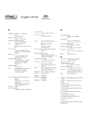
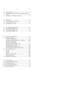
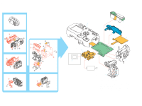
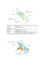
DSC-P41/P43 Section TABLE OF CONTENTS Title Page 1. SERVICE NOTE 1-1. Note for Repair 1-1 1-2. Discharging of the ST-098 Board's Charging Capacitor (C852 1-1 1-3. Description on Self-diagnosis Display 1-2 2. DISASSEMBLY 2-1. Flow Chart 2-1 2-2. SY-101 Board Service Position 2-3 2-3. Circuit Boards Location 2-5 2-4. Flexible Boards Location 2-5 3. BLOCK DIAGRAMS 3-1. Overall Block Diagram (1/2 3-1 3-2. Overall Block Diagram (2/2 3-3 3-3. Power Block Diagram (1/2 3-5 3-4. Power Block Diagram (2/2 3-7 4. PRINTED WIRING BOARDS AND SCHEMATIC DIAGRAMS 4-1. Frame Schematic Diagram 4-1 4-2. Schematic Diagrams 4-5 CD-501 (CCD IMAGER 4-7 SW-420 (CONTROL SWITCH, LCD DRIVE 4-27 ST-098 (FLASH DRIVE 4-29 MS (FP-861 FLEXIBLE) (MEMORY STICK CONNECTOR 4-31 FP-860 FLEXIBLE (JACK 4-32 MICROPHONE UNIT (MA-001 4-33 CONTROL SWITCH BLOCK (RL51510 4-34 4-3. Printed Wiring Boards 4-35 CD-501 4-37 SW-420 4-43 ST-098 4-45 MS (FP-861 FLEXIBLE 4-47 FP-860 FLEXIBLE 4-48 4-4. Mounted Parts Location 4-49 5. REPAIR PARTS LIST 5-1. Exploded Views 5-2 5-1-1. Front Cabinet Block Section 5-2 5-1-2. Lens Block Section 5-3 5-1-3. BT Holder Block Section 5-4 5-1-4. Rear Cabinet Block Section 5-5 5-2. Electrical Parts List 5-6 - 4 -
-
 1
1 -
 2
2 -
 3
3 -
 4
4 -
 5
5 -
 6
6 -
 7
7 -
 8
8 -
 9
9 -
 10
10 -
11
-
12
-
13
-
14
-
15
-
16
-
17
-
18
-
19
-
20
-
21
-
22
-
23
-
24
-
25
-
26
-
27
-
28
-
29
-
30
-
31
-
32
-
33
-
34
-
35
-
36
-
37
-
38
-
39
-
40
-
41
-
42
-
43
-
44
-
45
-
46
-
47
 |
 |