Sony DSC-T110 Instruction Manual - Page 11
Identifying parts
 |
UPC - 027242813359
View all Sony DSC-T110 manuals
Add to My Manuals
Save this manual to your list of manuals |
Page 11 highlights
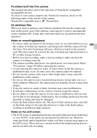
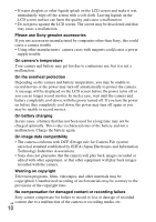
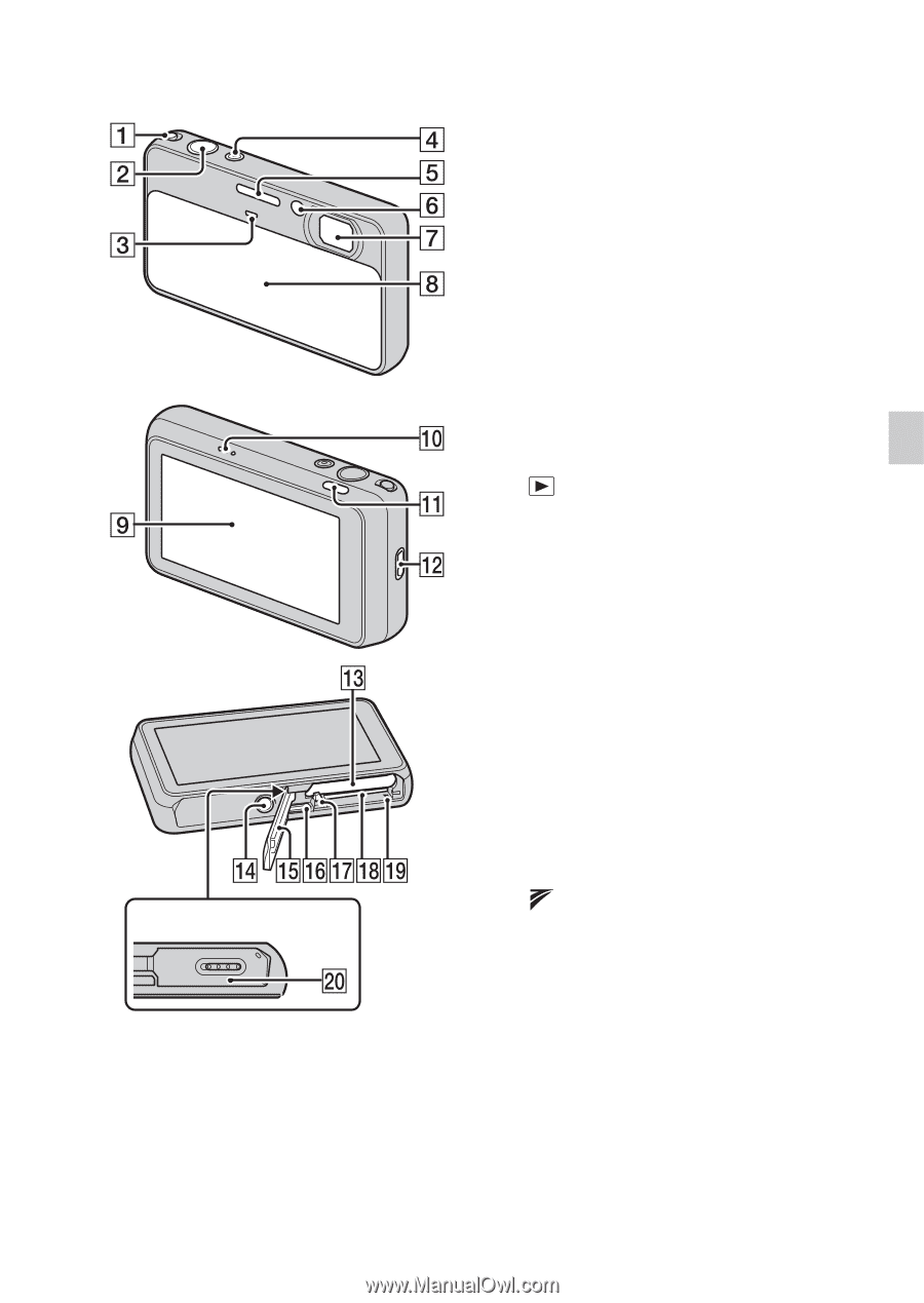
Identifying parts Cover panel A Zoom (W/T) lever B Shutter button C Microphone D ON/OFF (Power) button/ Power lamp E Flash F Self-timer lamp/Smile Shutter lamp/AF illuminator G Lens H Lens cover I LCD screen/Touch panel GB J Speaker K (Playback) button L Hook for wrist strap M Battery insertion slot N Tripod receptacle • Use a tripod with a screw less than 5.5 mm (7/32 inches) long. Otherwise, you cannot firmly secure the camera, and damage to the camera may occur. O Battery/Memory card cover P Multi-connector (Type3a) Q Battery eject lever R Memory card slot S Access lamp T (TransferJet™) mark GB 11
-
 1
1 -
2
-
3
-
4
-
5
-
 6
6 -
 7
7 -
 8
8 -
 9
9 -
 10
10 -
 11
11 -
 12
12 -
 13
13 -
 14
14 -
 15
15 -
 16
16 -
17
-
18
-
19
-
20
-
21
-
22
-
23
-
24
-
25
-
26
-
27
-
28
-
29
-
30
-
31
-
32
-
33
-
34
-
35
-
36
-
37
-
38
-
39
-
40
-
41
-
42
-
43
-
44
-
45
-
46
-
47
-
48
-
49
-
50
-
51
-
52
-
53
-
54
-
55
-
56
-
57
-
58
-
59
-
60
-
61
-
62
-
63
-
64
-
65
-
66
-
67
-
68
-
69
-
70
-
71
-
72
 |
 |
GB
11
GB
Identifying parts
A
Zoom (W/T) lever
B
Shutter button
C
Microphone
D
ON/OFF (Power) button/
Power lamp
E
Flash
F
Self-timer lamp/Smile Shutter
lamp/AF illuminator
G
Lens
H
Lens cover
I
LCD screen/Touch panel
J
Speaker
K
(Playback) button
L
Hook for wrist strap
M
Battery insertion slot
N
Tripod receptacle
•
Use a tripod with a screw less
than 5.5 mm (7/32 inches) long.
Otherwise, you cannot firmly
secure the camera, and damage to
the camera may occur.
O
Battery/Memory card cover
P
Multi-connector (Type3a)
Q
Battery eject lever
R
Memory card slot
S
Access lamp
T
(TransferJet™) mark
Cover panel