Sony DSC W55 Service Manual - Page 12
MC-181 Flexible Board, BT Holder Block - black
 |
UPC - 027242705432
View all Sony DSC W55 manuals
Add to My Manuals
Save this manual to your list of manuals |
Page 12 highlights
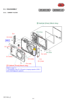
2-1-4. BT HOLDER BLOCK EXPLODED VIEW HARDWARE LIST 3-4 (#20) 1-4 (Note 1) WHITE BLACK RED SY-176 1-1 (#5) 3-2 1-3 (#20) 3-3 3-1 1-2 MC-181 HELP 3-6 HELP 3-5 1 SY-176 Board 2-1 (#20) 2-3 2-2 3 BT Holder Block 2 MC-181 Flexible Board Note 1 : Precaution 1-4 when exchanging BT terminal board (service) Refer to fig.2-1-1, when install BT terminal board (service) in BT holder block. Fig.2-1-2 is soldering position about BT terminal board (service). BLACK WHITE RED RED WHITE BLACK 1 2 fig.2-1-1 1. Install to BT holder block. 2. Break the notch. soldering three positions SY-176 BOARD (SIDE A) fig2-1-2 DSC-W55_L2 2-5
-
 1
1 -
2
-
3
-
4
-
5
-
6
-
 7
7 -
 8
8 -
 9
9 -
 10
10 -
 11
11 -
 12
12 -
 13
13 -
 14
14 -
 15
15 -
 16
16 -
 17
17 -
18
-
19
-
20
-
21
-
22
-
23
-
24
-
25
-
26
-
27
-
28
-
29
-
30
-
31
-
32
-
33
-
34
-
35
-
36
-
37
-
38
-
39
-
40
-
41
-
42
-
43
-
44
-
45
-
46
-
47
-
48
-
49
-
50
-
51
-
52
-
53
-
54
-
55
-
56
-
57
-
58
-
59
-
60
 |
 |

2-5
DSC-W55_L2
2-1-4.
BT
HOLDER
BLOCK
EXPLODED VIEW
HARDWARE LIST
1
SY-176 Board
1
-1 (#5)
1
-3
(#20)
BLACK
RED
WHITE
3
-3
1
-2
1
-4 (Note 1)
3
-1
3
-2
HELP
2
-1 (#20)
2
-2
2
-3
2
MC-181 Flexible Board
3
BT Holder Block
3
-4 (#20)
3
-6
3
-5
Refer to fig.2-1-1, when install BT terminal board (service)
in BT holder block.
Note 1 : Precaution
1
-4
when exchanging BT terminal board (service)
Fig.2-1-2 is soldering position about BT terminal board (service).
1
. Install to BT holder block.
2
. Break the notch.
fig.2-1-1
RED
BLACK
WHITE
2
1
RED
WHITE
BLACK
SY-176 BOARD (SIDE A)
soldering three
positions
fig2-1-2
SY-176
MC-181
HELP