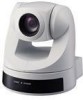
Sony EVI D70 Technical Manual - Page 6
Remote Commander, L/R DIRECTION SET button - manual
 |
View all Sony EVI D70 manuals
Add to My Manuals
Save this manual to your list of manuals |
Page 6 highlights
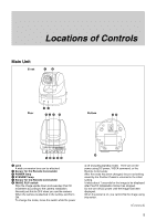
7 IR SELECT switch 8 VISCA RS-422 connector A VISCA RS-422 connector plug is attached to the unit at the factory. 9 VIDEO (output) connector 0 S VIDEO (output) connector qa VISCA RS-232C IN connector qs VISCA RS-232C OUT connector qd DC IN 12V connector qf Tripod screw hole qg BOTTOM switch D30 IR RS 38400 MODE OUT 422 bps OFF OFF RS 9600 232C bps 1234 1 D30/D31 mode switch Set this switch to ON to operate the Color Video Camera using the VISCA commands for the EVI-D30/ D31. (See page 52.) 2 IR SELECT switch Set this switch to ON to allow the camera output signals transmitted from the Remote Commander to the Color Video Camera via VISCA OUT jack. (See page 35.) 3 RS-232C/RS-422 SELECT switch Set this switch to RS422 to operate the Color Video Camera using the VISCA commands via the RS-422 interface. To switch modes, make sure that the power is turned off (excluding standby mode), move the BOTTOM switch, and then turn the DC power on. The unit will not switch modes after the power is turned on. 4 BAUD RATE SELECT switch Set this switch to 38400 bps to operate the camera with the baud rate of 38400 bps. To switch modes, make sure that the power is turned off (excluding standby mode), move the BOTTOM switch, and then turn the DC power on. The unit will not switch modes after the power is turned on. qh Ceiling bracket mounting screw holes Locations of Controls Remote Commander 1 2 3 4 5 POWER CAMERA SELECT 1 2 3 AUTO FOCUS MANUAL FAR NEAR DATA SCREEN BACK LIGHT STD REV 123 456 PRESET RESET POSITION PAN-TILT HOME PAN-TILT RESET SLOW ZOOM FAST TT W L/R DIRECTION SET W RM-EV100 6 7 8 9 q; 1 CAMERA SELECT buttons 2 FOCUS buttons AUTO button FAR button NEAR button MANUAL button 3 DATA SCREEN button When the DATA SCREEN button is pushed, the camera status is displayed when you are using the Zoom or Manual Focus functions. DATA SCREEN can be set to ON or OFF, and memorized, only with POSITION 1. When POSITION 1 is recalled, the memorized DATA SCREEN status is used. 4 PAN-TILT button Arrow buttons HOME button 5 L/R DIRECTION SET button 6 POWER switch 7 BACK LIGHT button 8 POSITION buttons Numeric buttons (Button 1 also works as the STD button. Button 2 also works as the REV button.) PRESET button RESET button 9 PAN-TILT RESET button 0 ZOOM buttons SLOW T button SLOW W button FAST T button FAST W button 6
-
 1
1 -
 2
2 -
 3
3 -
 4
4 -
 5
5 -
 6
6 -
 7
7 -
 8
8 -
 9
9 -
 10
10 -
 11
11 -
 12
12 -
13
-
14
-
15
-
16
-
17
-
18
-
19
-
20
-
21
-
22
-
23
-
24
-
25
-
26
-
27
-
28
-
29
-
30
-
31
-
32
-
33
-
34
-
35
-
36
-
37
-
38
-
39
-
40
-
41
-
42
-
43
-
44
-
45
-
46
-
47
-
48
-
49
-
50
-
51
-
52
-
53
-
54
-
55
-
56
-
57
-
58
-
59
-
60
-
61
 |
 |
