Sony F35 Product Manual (CAF101 Operations Manual 1st ED) - Page 25
Operation Check
 |
View all Sony F35 manuals
Add to My Manuals
Save this manual to your list of manuals |
Page 25 highlights
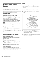
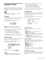
Operation Check When the F23/F35 is connected to the video recorder using this adapter, you can check the connection status on the subdisplay of the camera and a video monitor connected to the camera. Note F23/F35 before Ver 1.2 requires version upgrading. Consult Sony service personnel. Subdisplay You can check the optical level on the system status page of the subdisplay located on the side of the camera. For details on subdisplay operations, refer to the Operation Manual of the F23 or F35. CAM:xxxxxxxxb VTR:xxxxxxxxb CAM: Optical reception level on the camera side VTR: Optical reception level on the SRW-1 side The status of the level is indicated with eight segments. If 6 to 8 segments are lit: Normal If 3 to 5 segments are lit: Cautioning level If only 1 or 2 segments are lit: Warning level If no segment is lit: No signal or unusable level The meanings are the same as those of the OPT indicator of the adapter. For measures to be taken, see page 20. FUNCTION display The optical level can also be checked on the FUNCTION display on a monitor connected to the camera. For details on the FUNCTION display, refer to the Operation Manual of the F23 or F35. FUNCTION xxxxxxxxxxxxxxxxxxxxxxxx FORMAT: 59.94i 4:2:2 (30)FPS AS1:OFF AS2:OFF AS3:OFF AS4:OFF Level indications OPT LVL CAM:xxxxxxxxb V T R : xxxxxxxxb OPT LVL CAM: Optical reception level on the camera side VTR: Optical reception level on the SRW-1 side The status of the level is indicated with eight segments. If 6 to 8 segments are lit: Normal If 3 to 5 segments are lit: Cautioning level If only 1 or 2 segments are lit: Warning level If no segment is lit: No signal or unusable level The meanings are the same as those of the OPT indicator of the adapter. For measures to be taken, see page 20. DIAGNOSIS menu The page of the DIAGNOSIS menu displayed on a monitor connected to the camera shows the docking and optical statuses. For details on menu operations, refer to the Operation Manual of the F23 or F35. D01 TOP DOCKING STATUS TOP :--- REAR :OPT CA- VTR OPTICAL STATUS VTRtCAM :OK CAMtVTR :OK DOCKING STATUS Indicates the device docked on the top or rear of the camera. - - -: No device IF BOX: Interface box supplied with the camera VTR: SRW-1 video recorder OPT CA: CA-F101 (Changes to "OPT CA - VTR" when the camera is connected to the recorder via the adapter.) (IF BOX), (OPT CA): Indicated in parentheses if combination use of the docked device is not allowed. OPTICAL STATUS Indicates the optical reception status on the camera side (VTRtCAM) and that on the recorder side (CAMtVTR) while signal transmission is in progress. OK: Normal CARE: Cautioning level WARNING: Warning level NG: Unusable level NO SIGNAL: No signal The meanings are the same as those of the OPT indicator of the adapter. For the measures to be taken, see page 20. Warning/error message If a problem occurs in this unit, a warning is given by the following message indication on the viewfinder or monitor screen: 25 Operation Check
-
 1
1 -
2
-
3
-
4
-
5
-
6
-
7
-
8
-
9
-
10
-
11
-
12
-
13
-
14
-
15
-
16
-
17
-
18
-
19
-
 20
20 -
 21
21 -
 22
22 -
 23
23 -
 24
24 -
 25
25 -
 26
26 -
 27
27 -
 28
28 -
 29
29 -
 30
30 -
31
-
32
 |
 |
