Sony HCD-D390 Service Manual - Page 21
Tuner
 |
View all Sony HCD-D390 manuals
Add to My Manuals
Save this manual to your list of manuals |
Page 21 highlights
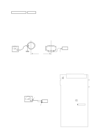
TUNER SECTION 0dB=1µV Note 1: As a front-end (FE1) is difficult to repair if faulty, replace it with new one. Note 2: No adjustment is needed due to a tuner pack for except AEP, UK, East European, CIS models. AM Tuned Level Adjustment Note: FM Tuned Level adjustment should be performed after this AM Tuned Level Adjustment. Setting: Band: MW loop antenna loop antenna (Supplied accessories) AM RF SSG set 30% amplitude modulation by 400 Hz signal 60 cm AM ANTENNA terminal (TM1) Field strength dB (µV/m) =SSG output level dB (µV/m) -26 dB. \Modulation: 999 kHz (at 9 kHz step) 1,050 kHz (at 10 kHz step) Procedure: 1. Set the output of SSG so that the input level of the set becomes 55 dB. 2. Tune the set to 999 kHz or 1,050 kHz. 3. Adjust RV41 to the point (moment) when the TUNED indicator will change from going off to going on. Adjustment Location: TCB board FM Tuned Level Adjustment Note: This adjustment should be performed after the AM Tuned Level Adjustment. Setting: Band: FM FM RF SSG 75 Ω coaxial set Carrier frequency : 98 MHz Modulation : AUDIO 1 kH, 75 kHz deviation (100%) FM ANTENNA Output level: 25db (at 75 Ω open) terminal (TM1) Adjustment Location: TCB board [TCB BOARD] (Component Side) TM1 RV41 AM Tuner Level RV42 FM Tuned Level IC21 Procedure: 1. Supply a 25 dB 98 MHz signal from the ANTENNA terminal. 2. Tune the set to 98 MHz. 3. Adjust RV42 to the point (moment) when the TUNED indicator will change from going off to going on. - 21 -
-
 1
1 -
2
-
3
-
4
-
5
-
6
-
7
-
8
-
9
-
10
-
11
-
12
-
13
-
14
-
15
-
 16
16 -
 17
17 -
 18
18 -
 19
19 -
 20
20 -
 21
21 -
 22
22 -
 23
23 -
 24
24 -
 25
25 -
 26
26 -
27
-
28
-
29
-
30
-
31
-
32
-
33
-
34
-
35
-
36
-
37
-
38
-
39
-
40
-
41
-
42
-
43
-
44
-
45
-
46
-
47
-
48
-
49
-
50
-
51
-
52
-
53
-
54
-
55
-
56
-
57
-
58
-
59
-
60
-
61
-
62
-
63
-
64
-
65
-
66
-
67
-
68
-
69
-
70
-
71
-
72
-
73
-
74
-
75
-
76
-
77
-
78
-
79
-
80
-
81
-
82
-
83
-
84
-
85
-
86
-
87
-
88
 |
 |
