Sony HCD-D390 Service Manual - Page 4
Electrical Parts List - motor
 |
View all Sony HCD-D390 manuals
Add to My Manuals
Save this manual to your list of manuals |
Page 4 highlights
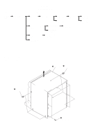
TABLE OF CONTENTS 1. GENERAL - FRONT PANEL 5 - BACK PANEL 6 2. DISASSEMBLY 8 3. TEST MODE 16 4. MECHANICAL ADJUSTMENTS 18 5. ELECTRICAL ADJUSTMENTS DECK Section 18 Tuner Section 21 CD Section 23 6. DIAGRAMS 6-1. Circuit Board Location 25 6-2. Block Diagrams - CD Section 26 - Tuner Section - (AEP, UK model 27 - Tuner Section - (East European, CIS model 29 - Main Section 31 6-3. Printed Wiring Board - BD Section 35 6-4 Schematic Diagram - BD Section 37 6-5. Printed Wiring Board - CD Motor Section 39 6-6. Schematic Diagram - CD Motor Section 41 6-7. Schematic Diagram - Tuner Section - (AEP, UK model 43 6-8. Printed Wiring Board - Tuner Section - (AEP, UK model 45 6-9. Printed Wiring Board - Tuner Section - (East European, CIS model 46 6-10. Schematic Diagram - Tuner Section - (East European, CIS model 47 6-11. Printed Wiring Board - Deck Section 49 6-12. Schematic Diagram - Deck Section 51 6-13. Schematic Diagram - Switch Section 53 6-14. Printed Wiring Board - Switch Section 55 6-15. Printed Wiring Board - Headphone-Mic Section 56 6-16. Schematic Diagram - Headphone-Mic Section 57 6-17. Printed Wiring Board - Panel Section 59 6-18. Schematic Diagram - Panel Section 61 6-19. Printed Wiring Board - Power Section 63 6-20. Schematic Diagram - Power Section 65 6-21. Printed Wiring Board - Main Section 67 6-22. Schematic Diagram - Main Section (1/5 69 6-23. Schematic Diagram - Main Section (2/5 71 6-24. Schematic Diagram - Main Section (3/5 73 6-25. Schematic Diagram - Main Section (4/5 75 6-26. Schematic Diagram - Main Section (5/5 77 6-27. IC Block Diagrams 79 6-28. IC Pin Function Description 84 7. EXPLODED VIEWS 87 8. ELECTRICAL PARTS LIST 96 SERVICING NOTES NOTES ON HANDLING THE OPTICAL PICK-UP BLOCK OR BASE UNIT The laser diode in the optical pick-up block may suffer electrostatic break-down because of the potential difference generated by the charged electrostatic load, etc. on clothing and the human body. During repair, pay attention to electrostatic break-down and also use the procedure in the printed matter which is included in the repair parts. The flexible board is easily damaged and should be handled with care. NOTES ON LASER DIODE EMISSION CHECK The laser beam on this model is concentrated so as to be focused on the disc reflective surface by the objective lens in the optical pickup block. Therefore, when checking the laser diode emission, observe from more than 30 cm away from the objective lens. MODEL IDENTIFICATION - BACK PANEL - PARTS No. MODEL XB33:E,Argentine models XB33:Mexican model XB33:Australian model XB33:South African model D390:US model D390:Canadian model XB50:AEP,UK models XB50:East European,CIS models G5500 XB44:E,Argentine models XB44:Mexican model XB44:Australian model XB44:South African model D790:US model D790:Canadian model XB60:AEP,UK models XB60:East European,CIS models PARTS No. 4-996-410-0π 4-996-410-2π 4-996-410-3π 4-996-410-4π 4-996-411-0π 4-996-411-1π 4-996-411-2π 4-996-411-3π 4-996-411-4π 4-996-412-0π 4-996-412-2π 4-996-412-3π 4-996-412-4π 4-996-419-0π 4-996-419-1π 4-996-419-2π 4-996-419-3π - 4 -
-
 1
1 -
 2
2 -
 3
3 -
 4
4 -
 5
5 -
 6
6 -
 7
7 -
 8
8 -
 9
9 -
 10
10 -
11
-
12
-
13
-
14
-
15
-
16
-
17
-
18
-
19
-
20
-
21
-
22
-
23
-
24
-
25
-
26
-
27
-
28
-
29
-
30
-
31
-
32
-
33
-
34
-
35
-
36
-
37
-
38
-
39
-
40
-
41
-
42
-
43
-
44
-
45
-
46
-
47
-
48
-
49
-
50
-
51
-
52
-
53
-
54
-
55
-
56
-
57
-
58
-
59
-
60
-
61
-
62
-
63
-
64
-
65
-
66
-
67
-
68
-
69
-
70
-
71
-
72
-
73
-
74
-
75
-
76
-
77
-
78
-
79
-
80
-
81
-
82
-
83
-
84
-
85
-
86
-
87
-
88
 |
 |
