Sony HCD-HPR90 Service Manual - Page 11
Belt Dlm3a, Optical, Pick-up, Block
 |
View all Sony HCD-HPR90 manuals
Add to My Manuals
Save this manual to your list of manuals |
Page 11 highlights
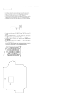
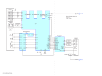
3-7. BELT (DLM3A) 3 four screws HCD-HPR90/HPR99XM 4 plate cam 2 Draw out the tray fully in the direction of the arrow B. B 5 two belts (DLM3A) A 1 Turn the lower gear in the direction of the arrow A, untill the upper gear gose up to the high position. 3-8. OPTICAL PICK-UP BLOCK 4 5 insulator 3 coil spring (insulator) 2 two screws (PTPWH M2.6) 3 coil spring (insulator) 7 CD board 5 insulator 3 coil spring (insulator) 8 optical pick-up block 5 insulator 5 insulator 3 coil spring (insulator) 2 two screws (PTPWH M2.6) 1 flexible flat (16 core) cable (CN301) 6 Remove four solders. 11
-
 1
1 -
2
-
3
-
4
-
5
-
 6
6 -
 7
7 -
 8
8 -
 9
9 -
 10
10 -
 11
11 -
 12
12 -
 13
13 -
 14
14 -
 15
15 -
 16
16 -
17
-
18
-
19
-
20
-
21
-
22
-
23
-
24
-
25
-
26
-
27
-
28
-
29
-
30
-
31
-
32
-
33
-
34
-
35
-
36
-
37
-
38
-
39
-
40
-
41
-
42
-
43
-
44
-
45
-
46
-
47
-
48
-
49
-
50
-
51
-
52
-
53
-
54
-
55
-
56
-
57
-
58
-
59
-
60
-
61
-
62
-
63
-
64
-
65
-
66
-
67
-
68
-
69
-
70
-
71
-
72
-
73
-
74
-
75
-
76
-
77
-
78
-
79
-
80
 |
 |

HCD-HPR90/HPR99XM
11
3-7.
BELT (DLM3A)
3-8.
OPTICAL
PICK-UP
BLOCK
3
four screws
4
plate cam
5
two belts
(DLM3A)
A
B
1
Turn the lower gear in the direction of the arrow
A
,
untill the upper gear gose up to the high position.
2
Draw out the tray fully in the
direction of the arrow
B
.
1
flexible flat (16 core) cable
(CN301)
2
two screws
(PTPWH M2.6)
6
Remove four solders.
2
two screws
(PTPWH M2.6)
3
coil spring (insulator)
3
coil spring (insulator)
3
coil spring (insulator)
4
3
coil spring (insulator)
5
insulator
5
insulator
7
CD board
8
optical pick-up block
5
insulator
5
insulator