Sony HDFX-200 Operation Guide - Page 3
Overview, Locations and Functions, of Parts
 |
View all Sony HDFX-200 manuals
Add to My Manuals
Save this manual to your list of manuals |
Page 3 highlights
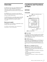
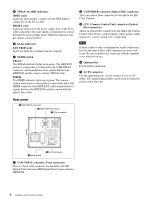
Overview The HD Digital Triax CCU Adaptor HDFX200 and HD Triax Camera Adaptor HDTX200 are designed for connecting a camera to a camera control unit and converting the link format between them from optical fiber to Triax. The HDFX200 can be connected by optical fiber and Triax, and switched remotely between them for the useful function of Outdoor Broadcasting. The HDTX200 links the optical fiber connector of the HD camera to the Triax connector of the HD Digital Triax CCU Adaptor HDFX200, providing the required conversion. Rack mount capable The HDFX200 can be installed in a standard EIA 19-inch rack (up to three units in 3U space). For details on rack mounting, contact a Sony Service representative or Sales representative. Locations and Functions of Parts HDFX200 Front panel 3OPTICAL CONDITION indicators 2POWER indicators 1Power switch OPTICAL CONDITION CAM CCU HDFX POWER CAM MAIN MODE TRIAX TRIAX ALARM OPEN SHORT FIBER FAN STOP DIGITAL TRIAX PROGRESSIVE HD DIGITAL TRIAX CCU ADAPTOR HDFX200 6MODE switch 5Status indicators 4TRIAX ALARM indicators a Power switch This switch controls power to the entire system including the HDFX200, video camera, HD Digital Triax Camera Adaptor HDTX200, etc. In the "@" position, power is on. In the "a" position, power is off. b POWER indicators When power is on, the MAIN indicator and CAM indicator light up. When the CAM POWER switch on the Master Setup Unit or the Remote Control Panel is pressed, only the camera power is turned off and the CAM indicator goes out. c OPTICAL CONDITION indicators Displays the optical signal receiving condition of the HDFX200 from a camera or Camera Control Unit. • Two green indicators light up (3rd and 4th indicators): Reception is very good. • One green indicator lights up (3rd indicator): Reception is good. • The yellow indicator lights up (2nd indicator): Reception is poor. • The red indicator lights up (1st indicator): Reception is very poor. 3 Overview / Locations and Functions of Parts
-
 1
1 -
 2
2 -
 3
3 -
 4
4 -
 5
5 -
 6
6 -
 7
7 -
 8
8 -
 9
9 -
10
-
11
-
12
-
13
-
14
-
15
-
16
-
17
-
18
-
19
-
20
-
21
-
22
-
23
-
24
-
25
-
26
-
27
 |
 |
