Sony HDWM2100/20 Operation Manual - Page 24
TIME CODE OUT connector XLR 3-pin, male, MONITOR OUTPUT R connector XLR 3-pin
 |
View all Sony HDWM2100/20 manuals
Add to My Manuals
Save this manual to your list of manuals |
Page 24 highlights
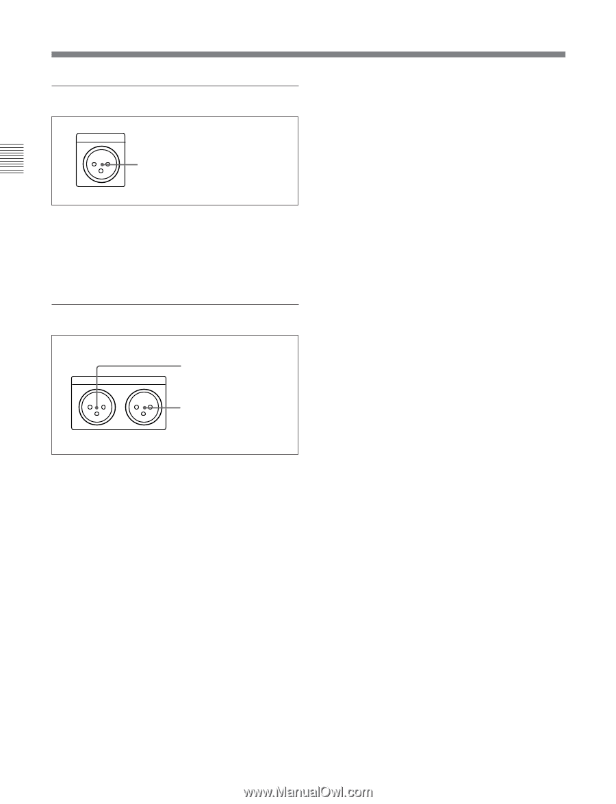
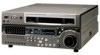
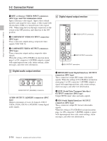
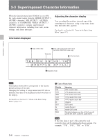
Chapter 2 Location and Function of Parts 2-2 Connector Panel 7 Time code output section TIME CODE OUT TIME CODE OUT connector TIME CODE OUT connector (XLR 3-pin, male) This outputs the playback time code. By setting setup menu item 606, you can also output the time code from the internal time code generator locked to the playback time code. 8 Audio monitor signal output section MONITOR OUTPUT R L 1 MONITOR OUTPUT R connector 2 MONITOR OUTPUT L connector 1 MONITOR OUTPUT R connector (XLR 3-pin, male) This outputs the audio signals whose output destination was set to 'R' with the audio signal selection buttons in the audio control section. If multiple tracks have been set to 'R', the signals of those tracks are mixed for output. 2 MONITOR OUTPUT L connector (XLR 3-pin, male) This outputs the audio signals whose output destination was set to 'L' with the audio signal selection buttons in the audio control section. If multiple tracks have been set to 'L', the signals of those tracks are mixed for output. 2-16 Chapter 2 Location and Function of Parts
-
 1
1 -
2
-
3
-
4
-
5
-
6
-
7
-
8
-
9
-
10
-
11
-
12
-
13
-
14
-
15
-
16
-
17
-
18
-
 19
19 -
 20
20 -
 21
21 -
 22
22 -
 23
23 -
 24
24 -
 25
25 -
 26
26 -
 27
27 -
 28
28 -
 29
29 -
30
-
31
-
32
-
33
-
34
-
35
-
36
-
37
-
38
-
39
-
40
-
41
-
42
-
43
-
44
-
45
-
46
-
47
-
48
-
49
-
50
-
51
-
52
-
53
-
54
-
55
-
56
-
57
-
58
-
59
-
60
-
61
-
62
-
63
-
64
-
65
-
66
-
67
-
68
-
69
-
70
-
71
-
72
-
73
-
74
-
75
-
76
-
77
-
78
-
79
-
80
-
81
-
82
-
83
-
84
-
85
-
86
-
87
-
88
-
89
-
90
-
91
-
92
-
93
-
94
-
95
-
96
-
97
-
98
-
99
-
100
-
101
-
102
-
103
-
104
-
105
-
106
-
107
-
108
-
109
-
110
-
111
-
112
-
113
-
114
-
115
 |
 |