Sony J10 Product Manual (j10 installtion manual)
Sony J10 Manual
 |
View all Sony J10 manuals
Add to My Manuals
Save this manual to your list of manuals |
Sony J10 manual content summary:
- Sony J10 | Product Manual (j10 installtion manual) - Page 1
i.LINK INTERFACE BOARD HKJ-101 INSTALLATION MANUAL 1st Edition - Sony J10 | Product Manual (j10 installtion manual) - Page 2
! WARNING This manual is intended for qualified service personnel only. To reduce the risk of electric shock, fire or injury, do not perform any servicing other than that contained in the operating instructions unless you are qualified to do so. Refer all servicing to qualified service personnel. ! - Sony J10 | Product Manual (j10 installtion manual) - Page 3
and, if not installed and used in accordance with the instruction manual, may cause harmful interference to radio communications. Operation of that may cause undesired operation. For customers in Canada This Class A digital apparatus complies with Canadian ICES-003. Pour les utilisateurs au Canada - Sony J10 | Product Manual (j10 installtion manual) - Page 4
- Sony J10 | Product Manual (j10 installtion manual) - Page 5
Digital Guide (Supplied with J-H1/J-H3) This manual serves as a quick reference. . J-H Series Maintenance Manual (e-manual) (Available on request) This manual describes the information that premises the component service this manual required, please contact your local Sony Sales Office/Service - Sony J10 | Product Manual (j10 installtion manual) - Page 6
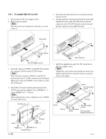
1-2-1. To install HKJ-101 in J-H1 1. Remove the six M3 case stopper screws. 2. Remove the rear panel. n Store the removed rear panel in a safe place so as not to lose it. 5. Insert the CN-2478 board to the second slot from the bottom of J-H1. 6. Strongly push the connector panel both from the right - Sony J10 | Product Manual (j10 installtion manual) - Page 7
1-2-2. To install HKJ-101 in J-H3 1. Remove the six M3 case stopper screws. 2. Remove the rear panel. n Store the removed rear panel in a safe place so as not to lose it. Rear panel M3 case stopper screws 4. Insert the connector (CN601) on the DV-29 board into the connector (CN41) on the SDI-80 - Sony J10 | Product Manual (j10 installtion manual) - Page 8
8. Install the supplied rear panel for J-H3 using the six M3 case stopper screws . n Tighten the screws in the state that the two dowels are aligned with the holes (a) and (b) on the rear panel as shown in the figure. Dowel M3 case stopper screws Hole (b) Dowel Hole (a) M3 case stopper screws - Sony J10 | Product Manual (j10 installtion manual) - Page 9
operation or maintenance of the equipment described in this manual without the express written permission of Sony Corporation. Le matériel contenu dans ce manuel consiste en informations qui sont la propriété de Sony Corporation. Sony Corporation interdit formellement la copie de quelque partie que - Sony J10 | Product Manual (j10 installtion manual) - Page 10
HKJ-101 (SY) J, E 3-805-991-01 Sony Corporation B&P Company Printed in Japan 2003. 7 16 ©2003
-
 1
1 -
 2
2 -
 3
3 -
 4
4 -
 5
5 -
 6
6 -
 7
7 -
8
-
9
-
10
 |
 |

i.LINK INTERFACE BOARD
HKJ-101
INSTALLATION MANUAL
1st Edition