Sony J10 Product Manual (j10 installtion manual) - Page 6
To install HKJ-101 in J-H1
 |
View all Sony J10 manuals
Add to My Manuals
Save this manual to your list of manuals |
Page 6 highlights
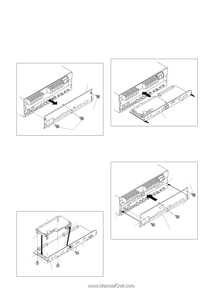
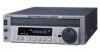
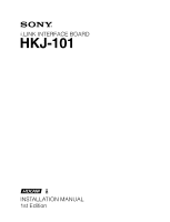
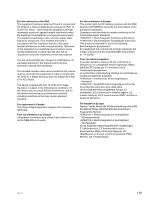
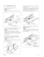
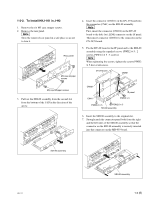
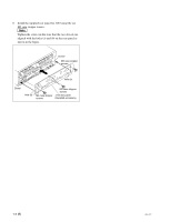
1-2-1. To install HKJ-101 in J-H1 1. Remove the six M3 case stopper screws. 2. Remove the rear panel. n Store the removed rear panel in a safe place so as not to lose it. 5. Insert the CN-2478 board to the second slot from the bottom of J-H1. 6. Strongly push the connector panel both from the right and the left sides of the CN-2478 board so that the connector on the CN-2478 board is securely inserted into the connector on the MB-993 board. Rear panel M3 case stopper screws CN-2478 board M3 case stopper screws 3. Insert the connector (CN601) on the DV-29 board into the connector (CN41) on the CN-2478 board. n First, insert the connector (CN401) on the DV-29 board to the hole for i.LINK connector on the IF panel. Then insert connector (CN601) to the connector on the CN-2478 board. 4. Fix the DV-29 board to the IF panel and to the CN2478 board using the supplied screws (PWH2 x 5 : 2 screws, PSW2.6 x 5 : 3 screws). n When tightening the screws, tighten the screws PWH2 x 5 first of all screws. DV-29 board CN401 CN601 IF panel CN41 PWH2 x 5 PSW2.6 x 5 PSW2.6 x 5 CN-2478 board 1-2 (E) 7. Install the supplied rear panel for J-H1 using the six M3 case stopper screws. n Tighten the screws in the state that the two dowels are aligned with the holes (a) and (b) on the rear panel as shown in the figure. Dowel M3 case stopper screws Hole (b) Dowel Hole (a) M3 case stopper screws M3 case stopper screws J-H1 rear panel (Supplied accessory) HKJ-101
-
 1
1 -
 2
2 -
 3
3 -
 4
4 -
 5
5 -
 6
6 -
 7
7 -
 8
8 -
 9
9 -
 10
10
 |
 |