Sony J10 Product Manual (j10 installtion manual) - Page 7
To install HKJ-101 in J-H3
 |
View all Sony J10 manuals
Add to My Manuals
Save this manual to your list of manuals |
Page 7 highlights
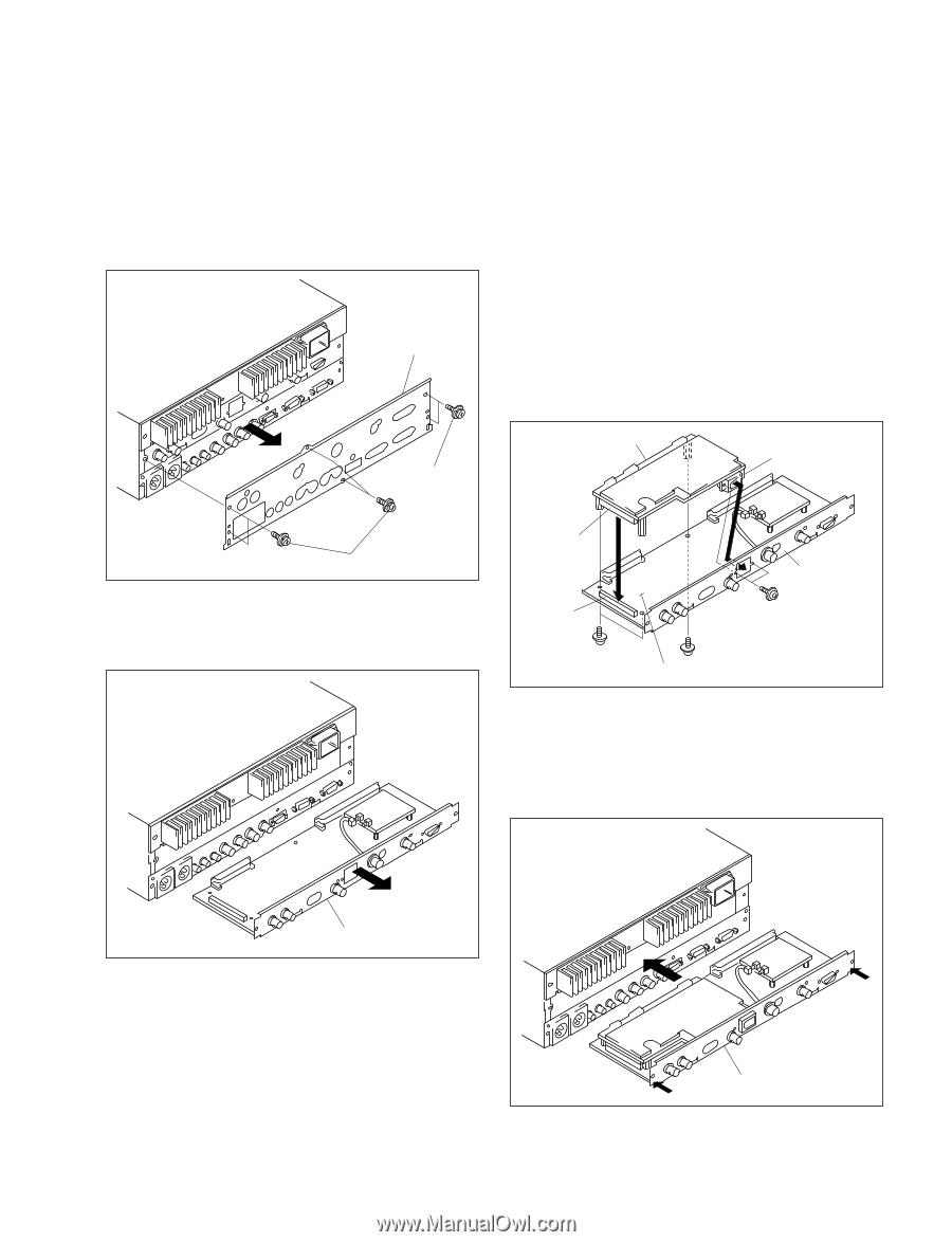
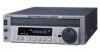
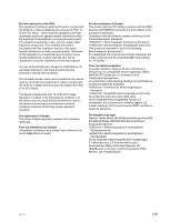
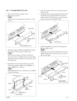
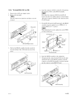
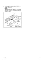
1-2-2. To install HKJ-101 in J-H3 1. Remove the six M3 case stopper screws. 2. Remove the rear panel. n Store the removed rear panel in a safe place so as not to lose it. Rear panel M3 case stopper screws 4. Insert the connector (CN601) on the DV-29 board into the connector (CN41) on the SDI-80 assembly. n First, insert the connector (CN401) on the DV-29 board to the hole for i.LINK connector on the IF panel. Then insert connector (CN601) to the connector on the CN-2478 board. 5. Fix the DV-29 board to the IF panel and to the SDI-80 assembly using the supplied screws (PWH2 x 5 : 2 screws, PSW2.6 x 5 : 3 screws). n When tightening the screws, tighten the screws PWH2 x 5 first of all screws. DV-29 board CN401 M3 case stopper screws 3. Pull out the SDI-80 assembly from the second slot from the bottom of the J-H3 in the direction of the arrow. CN601 IF panel CN41 PWH2 x 5 PSW2.6 x 5 PSW2.6 x 5 SDI-80 assembly 6. Insert the SDI-80 assembly to the original slot. 7. Strongly push the connector panel both from the right and the left sides of the SDI-80 assembly so that the connector on the SDI-80 assembly is securely inserted into the connector on the MB-993 board. SDI-80 assembly HKJ-101 SDI-80 assembly 1-3 (E)
-
 1
1 -
 2
2 -
 3
3 -
 4
4 -
 5
5 -
 6
6 -
 7
7 -
 8
8 -
 9
9 -
 10
10
 |
 |