Sony KLHW26 Operating Instructions - Page 41
Optional Adaptors, VIDEO INPUT Adaptor BKM-FW10, RGB/COMPONENT ACTIVE THROUGH, Adaptor BKM-FW12
 |
UPC - 027242238817
View all Sony KLHW26 manuals
Add to My Manuals
Save this manual to your list of manuals |
Page 41 highlights
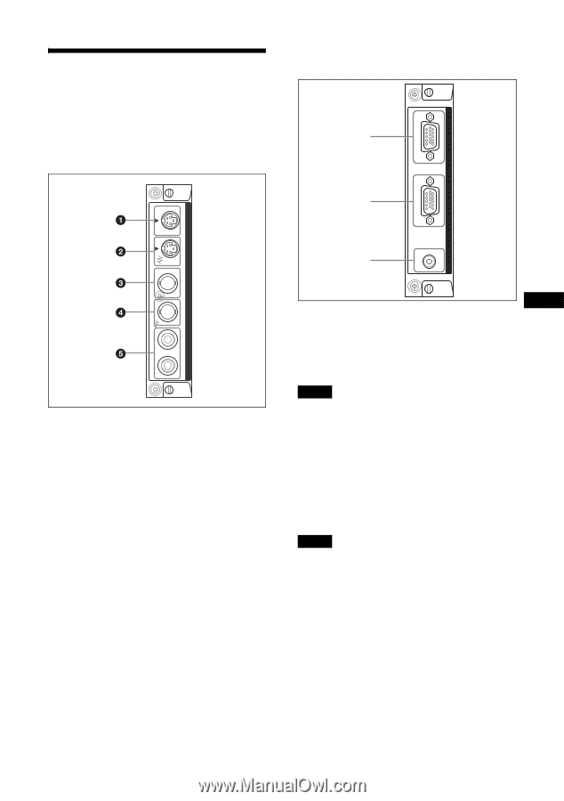
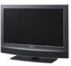
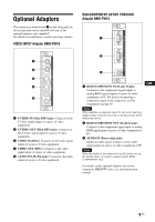
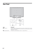
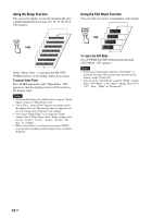
Optional Adaptors The connectors marked with 4 on the side panel are slot-in type and can be installed with any of the optional adaptors (not supplied). For details on installation, consult your Sony dealers. VIDEO INPUT Adaptor BKM-FW10 RGB/COMPONENT ACTIVE THROUGH Adaptor BKM-FW12 1 IN 2 RGB/COMPONENT ACTIVE THROUGH OUT S VIDEO IN AUDIO VIDEO INPUT ADAPTOR OUT 1 S VIDEO IN (Mini DIN 4-pin): Connects to the S Video signal output of a piece of video equipment. 2 S VIDEO OUT (Mini DIN 4-pin): Connects to the S Video signal input of a piece of video equipment. 3 VIDEO IN (BNC): Connects to the video signal output of a piece of video equipment. 4 VIDEO OUT (BNC): Connects to the video signal input of a piece of video equipment. 5 AUDIO IN L/R (Pin jack): Connects to the audio output of a piece of video equipment. R L OUT IN AUDIO IN VIDEO IN 3 1 RGB/COMPONENT IN (D-sub 15-pin): Connects to the component signal output or analog RGB signal output of a piece of video equipment or PC. For details on inputting a component signal to the connector, see Pin assignment on page 29 . Note When inputting a component signal, be sure not to input sync signals to pins 13 and 14. If you do so, the picture may not be displayed properly. 2 RGB/COMPONENT OUT (D-sub 15-pin): Connects to the component signal input or analog RGB signal input of a piece of video equipment or PC. 3 AUDIO IN (Stereo mini jack): Inputs an audio signal. Connects to the audio signal output of a piece of video equipment or PC. Note When the display is not connected to an AC power or is in the standby mode, no signal is output from the RGB/ COMPONENT OUT. GB For details on the optional adaptors for system expansion, BKM-FW series, see each instruction manual. 9 GB
-
 1
1 -
2
-
3
-
4
-
5
-
6
-
7
-
8
-
9
-
10
-
11
-
12
-
13
-
14
-
15
-
16
-
17
-
18
-
19
-
20
-
21
-
22
-
23
-
24
-
25
-
26
-
27
-
28
-
29
-
30
-
31
-
32
-
33
-
34
-
35
-
 36
36 -
 37
37 -
 38
38 -
 39
39 -
 40
40 -
 41
41 -
 42
42 -
 43
43 -
 44
44 -
 45
45 -
 46
46 -
47
-
48
-
49
-
50
-
51
-
52
-
53
-
54
-
55
-
56
-
57
-
58
-
59
-
60
-
61
-
62
-
63
-
64
-
65
-
66
-
67
-
68
-
69
-
70
-
71
-
72
-
73
-
74
-
75
-
76
-
77
-
78
-
79
-
80
-
81
-
82
-
83
-
84
-
85
-
86
-
87
-
88
-
89
-
90
-
91
-
92
-
93
-
94
-
95
-
96
-
97
-
98
-
99
-
100
-
101
-
102
-
103
-
104
-
105
-
106
-
107
-
108
-
109
-
110
-
111
-
112
-
113
-
114
-
115
-
116
-
117
-
118
-
119
-
120
-
121
-
122
-
123
-
124
-
125
-
126
-
127
-
128
-
129
-
130
-
131
-
132
-
133
-
134
-
135
-
136
-
137
-
138
-
139
-
140
-
141
-
142
-
143
-
144
-
145
-
146
-
147
-
148
-
149
-
150
-
151
-
152
-
153
-
154
-
155
-
156
-
157
-
158
-
159
-
160
-
161
-
162
-
163
-
164
-
165
-
166
-
167
-
168
-
169
-
170
-
171
-
172
-
173
-
174
-
175
-
176
-
177
-
178
-
179
-
180
-
181
-
182
-
183
-
184
-
185
-
186
-
187
-
188
-
189
-
190
-
191
-
192
-
193
-
194
-
195
-
196
-
197
-
198
-
199
-
200
-
201
-
202
-
203
-
204
-
205
-
206
-
207
-
208
-
209
-
210
-
211
-
212
-
213
-
214
-
215
 |
 |