Sony PCV-RS613GX Quick Start Guide - Page 37
To connect the telephone and modem cables
 |
View all Sony PCV-RS613GX manuals
Add to My Manuals
Save this manual to your list of manuals |
Page 37 highlights
Connecting the Telephone and Modem Cables To connect the telephone and modem cables "1-to-2" jack adapter (splitter - optional) Modem line jack 4 Insert the plug end of the splitter device into the wall jack. 5 Plug the modem cable into the modem line jack located on the back panel of the computer. Your computer has a protective sticker covering the Ethernet port located on the rear panel. Connect only 10BASE-T and 100BASE-TX cables to the Ethernet port. Using other cables or a telephone cable may result in an electric current overload that can cause a malfunction, excessive heat, or fire in the Ethernet port. For help on connecting to a network, see your network administrator. 37
-
 1
1 -
2
-
3
-
4
-
5
-
6
-
7
-
8
-
9
-
10
-
11
-
12
-
13
-
14
-
15
-
16
-
17
-
18
-
19
-
20
-
21
-
22
-
23
-
24
-
25
-
26
-
27
-
28
-
29
-
30
-
31
-
 32
32 -
 33
33 -
 34
34 -
 35
35 -
 36
36 -
 37
37 -
 38
38 -
 39
39 -
 40
40 -
 41
41 -
 42
42 -
43
-
44
-
45
-
46
-
47
-
48
 |
 |
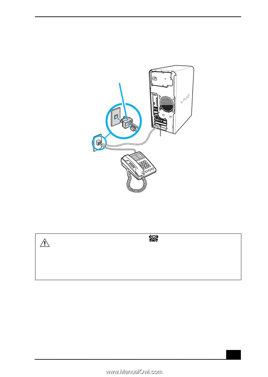
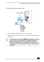
Connecting the Telephone and Modem Cables
37
4
Insert the plug end of the splitter device into the wall jack.
5
Plug the modem cable into the modem line jack located on the back panel of
the computer.
To connect the telephone and modem cables
Your computer has a protective sticker
covering the Ethernet port located
on the rear panel. Connect only 10BASE-T and 100BASE-TX cables to the
Ethernet port. Using other cables or a telephone cable may result in an
electric current overload that can cause a malfunction, excessive heat, or fire
in the Ethernet port. For help on connecting to a network, see your network
administrator.
“1-to-2” jack adapter
(splitter - optional)
Modem line jack