Sony PRS 505 Service Manual - Page 11
Prs-505, Electrical, Adjustment - reset
 |
UPC - 027242723665
View all Sony PRS 505 manuals
Add to My Manuals
Save this manual to your list of manuals |
Page 11 highlights
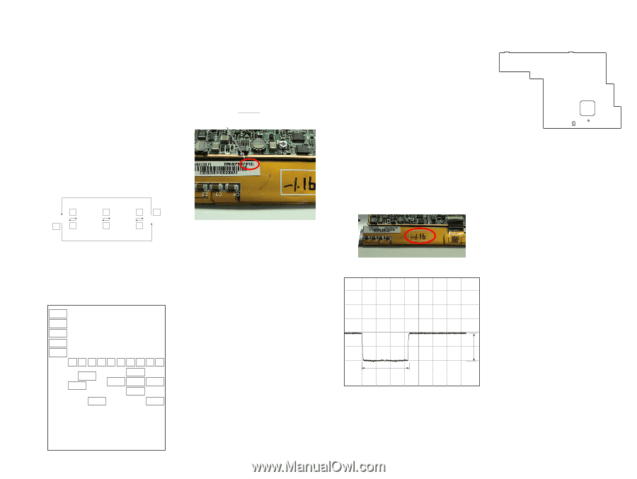
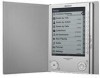
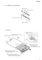
SECTION 4 TEST MODE HOW TO MAKE THE SD MEMORY CARD OR MEMORY STICK FOR TEST MODE USE ONLY 1. Ready for the SD memory card or memory stick. 2. Make the new directly as "/Sony Reader/software" on the SD memory card or memory stick. 3. Download the as follow as the files from internet site, copy to directly. Download files: autorun.xml, icon.png, key.png, lut.bin (If this download file's name is different, change to this name.) HOW TO ENTER THE TEST MODE 1. Insert the test mode SD memory card or memory stick. 2. After a while, indicate the test mode menu, enter the test mode. 3. The display invert when each button is pushed, and the display is back to the all button. 4. After the end of test, a display of the right side of Test Panel on TEST MODE MENU is changed to "Done" from "Not Yet". 3. Update Waveform In this mode, it is possible to confirm the variation of LUT (Look Up Table) and rewrite. The change of the LUT is required when a INK INDICATOR ELEMENT, MAIN BOARD and FLASH ROM (IC1203) are replaced. However, a INK INDICATOR ELEMENT is different from parameter by each lot number, therefore, rewriting is not required if the lot number is the same. The lot number is written on the label on the flexible board. lot number 1. Test Panel 1. While the machine selected tab "Test Panel" in test mode menu, press the [ENTER] button or [1] button. 2. Screen is changed to the Test Panel. 3. The display is changed so bellow with each time of pushing the [>] button or [ > > > WHITE LIGHT GRAY DARK GRAY BLACK < < < < 4. It's back to TEST MODE MENU when the [MENU] button. 5. After the end of test, a display of Test Panel on TEST MODE MENU is changed to "Done" from "Not Yet". 2. Check All Key 1. In the state that a Check All Key tab of TEST MODE MENU is selected, press the [ENTER] button or [2] button. 2. The screen is switched into the Check All Key state. NEXT PREV VOL+ VOLSIZE 1234 NEXT PREV MARK 56 LEFT 78 UP ENTER DOWN 90 RIGHT MENU 1. The current LUT version displayed at the right side of Update Waveform on TEST MODE MENU. 2. In the state that a Update Waveform tab is selected if it is press the [ENTER] button or [3] button, it starts rewriting LUT version. Note: It is necessary to match the LUT version to the version in elation to the lot number of the INK INDICATOR ELEMENT. Refer to Technical News about details. 3. After a few minutes (about 10 seconds), the screen display is refreshed, a LUT version display of the right side of Update Waveform on TEST MODE MENU is refreshed. 4. Reset Screen Lock The screen lock can be compulsorily released. 1. The current state of screen lock and the password are dis- played on the right side of Reset Screen Lock of TEST MODE MENU. 2. In the state that the Reset Screen Lock tab of TEST MODE MENU is selected, press the [ENTER] button or [4] button. 3. The display on the right side of Reset Screen Lock is changed to "Off-0000", so Screen Lock is unlocked . 5. Power Off 1. In the state of a Power Off tab of TEST MODE MENU, press the [ENTER] button or [5] button. 2. After a while, the screen display is changed white, so power is turned off. 6. Factory Initialize It return to the state various setting are shipped in the factory. The file of Flash ROM deletes all files except file the factory is shipped. Please note it enough you operate this mode. 1. In the state of a Factory Initialize tab of TEST MODE MENU, press the [ENTER] button or [6] button. 2. Initialize end. After a while, the screen display is changed white, so power is turned off. PRS-505 11 SECTION 5 ELECTRICAL ADJUSTMENT PRS-505 VCOM VOLTAGE ADJUSTMENT Vcom voltage for the display panel varies for each panel. VCOM adjustment is required when replacing a board or panel. Adjustment Location: - MAIN Board (Component Side) - Preparation: Voltage is generated only when the screen is changed, so the adjustment needs to be performed while changing the screen. Use the slideshow function to change the screen sequentially. 1. With the "Settings" tab in the menu selected, press the [EN- TER] button or the [0] button. 2. With the "Slideshow" tab selected, press the [ENTER] button or the [3] button. 3. Set "Turn On, Slide Duration 05 seconds", and press the [EN- TER] button on OK. Procedure: 1. With the "Pictures" tab in the menu selected, press the [EN- TER] button or the [9] button. 2. Specify a desired screen, and press the [ENTER] button to check that the slideshow starts. 3. Observe the TP354 on an oscilloscope (refer to Fig.2), and use RV1801 to adjust the voltage that is generated when the screen is changed so that it satisfies the standard. RV1801 IC301 TP354 Standard: Written on the flexible card wire of the display panel with a marker. (-1 V to -2.5 V) (Refer to following Fig.1) (In case of Fig.1: The value of VCOM is -1.16 V.) Fig. 1 660 ms 500 mV/DIV, 200 ms/DIV Fig. 2 1 Vp-p 11
-
 1
1 -
2
-
3
-
4
-
5
-
 6
6 -
 7
7 -
 8
8 -
 9
9 -
 10
10 -
 11
11 -
 12
12 -
 13
13 -
 14
14 -
 15
15 -
 16
16 -
17
-
18
-
19
-
20
-
21
-
22
-
23
-
24
-
25
-
26
-
27
-
28
-
29
-
30
-
31
-
32
-
33
-
34
-
35
-
36
-
37
-
38
-
39
-
40
-
41
-
42
-
43
-
44
-
45
-
46
-
47
-
48
-
49
-
50
-
51
-
52
-
53
-
54
-
55
-
56
-
57
-
58
-
59
-
60
-
61
-
62
-
63
-
64
-
65
-
66
-
67
-
68
-
69
-
70
-
71
-
72
-
73
-
74
 |
 |