Sony PVM-X1800 Operating Instructions - Page 13
Rear Panel, HDMI IN HDMI input connector
 |
View all Sony PVM-X1800 manuals
Add to My Manuals
Save this manual to your list of manuals |
Page 13 highlights
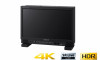
Rear Panel Handle (For PVM-X2400 only) When using the handle on PVM-X1800, attach the supplied handle according to the steps on page 16. LAN (10/100) connector Connect to the controller or an external device by using a 10BASE-T/100BASE-TX LAN cable (shielded type, optional). Note The connection speed may be affected by the network system. This unit does not guarantee the communication speed or quality of 10BASET/100BASE-TX. PARALLEL REMOTE connector (RJ-45, 8pin) Forms a parallel control switch and controls this unit externally. Pin assignment Pin number 1 2 3 4 5 Functions "Ch.1" is specified. "Ch.2" is specified. "Ch.3" is specified. "Ch.4" is specified. GND Pin number 6 7 8 Functions All the markers set under "Marker Preset" in the "User Preset Setting" menu are all turned on at once. Tally Green Tally Red Wiring required to use the Remote Control Connect the function you want to use with a Remote Control to the Ground (Pin 5). HDMI IN (HDMI input) connector Input connector for HDMI signals. HDMI (High-Definition Multimedia Interface) is an interface that supports both video and audio on a single digital connection, allowing you to enjoy high quality digital picture and sound. The HDMI specification supports HDCP (Highbandwidth Digital Content Protection), a copy protection technology that incorporates coding technology for digital video signals. Note To input the HDMI signal equivalent to 4K, use an HDMI cable bearing the Premium High Speed logo within a length of 3 meters (Sony product recommended). To input other signals, we also recommend using a Premium High Speed HDMI cable within a length of 3 meters. AUDIO output connector (stereo mini jack) The input audio signal set in the currently selected channel is output. 13
-
 1
1 -
2
-
3
-
4
-
5
-
6
-
7
-
 8
8 -
 9
9 -
 10
10 -
 11
11 -
 12
12 -
 13
13 -
 14
14 -
 15
15 -
 16
16 -
 17
17 -
 18
18 -
19
-
20
-
21
-
22
-
23
-
24
-
25
-
26
-
27
-
28
-
29
-
30
-
31
-
32
-
33
-
34
-
35
-
36
-
37
-
38
-
39
-
40
-
41
-
42
-
43
-
44
-
45
-
46
-
47
-
48
-
49
-
50
-
51
-
52
-
53
-
54
-
55
 |
 |
