Sony STR-AV570 Operating Instructions - Page 2
Connections - receiver
 |
View all Sony STR-AV570 manuals
Add to My Manuals
Save this manual to your list of manuals |
Page 2 highlights
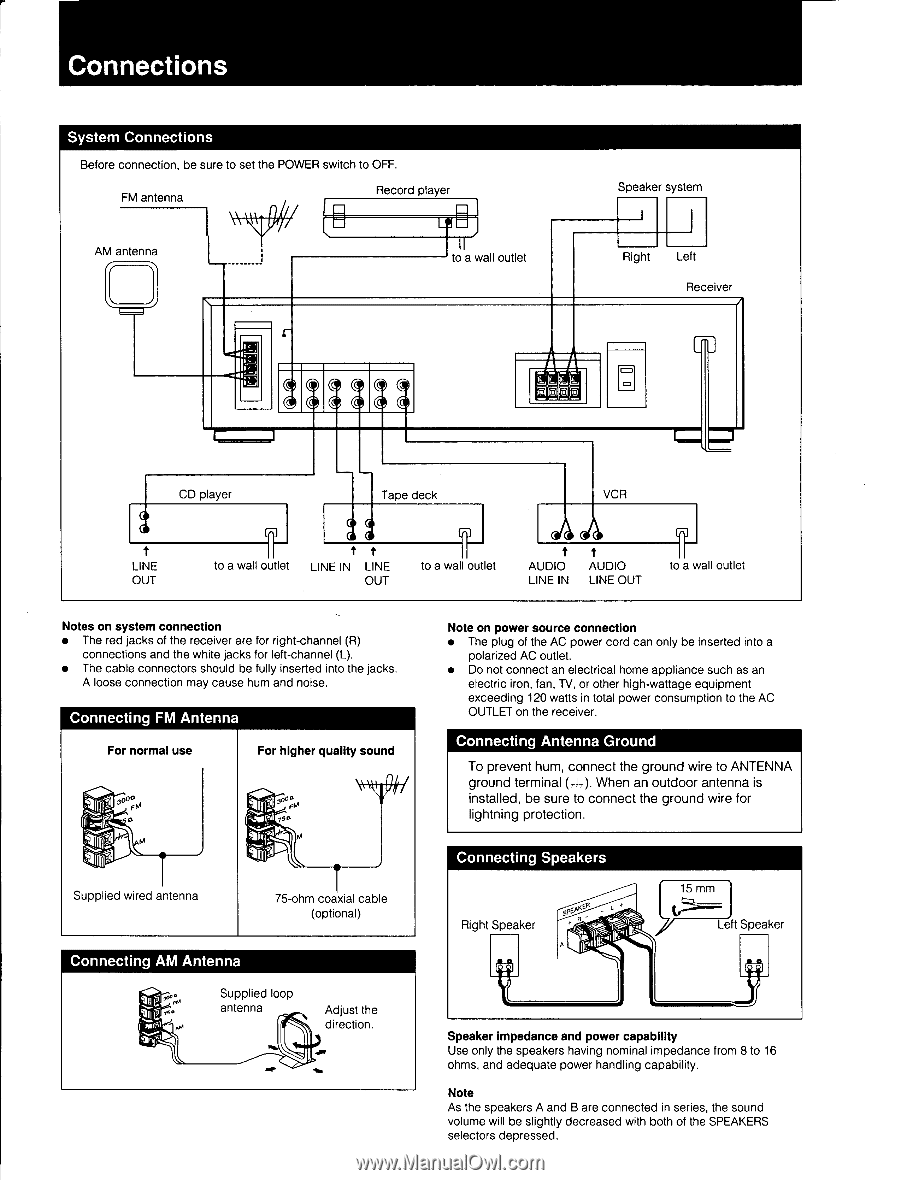
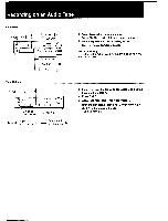
Connections System Connections Before connection, be sure to set the POWER switch to OFF. FM antenna Record player AM antenna to a wall outlet :;4133 Speaker system Right Left Receiver L j CD player O LINE OUT to a wall outle Tape deck 0 0 0 al t t LINE IN LINE OUT to a wall outlet VCR t AUDIO LINE IN t AUDIO LINE OUT to a wall outlet Notes on system connection • The red jacks of the receiver are for right-channel (R) connections and the white jacks for left-channel (L). • The cable connectors should be fully inserted into the jacks. A loose connection may cause hum and noise. Connecting FM Antenna For normal use For higher quality sound 50? 0 Igo Supplied wired antenna 75-ohm coaxial cable (optional) Connecting AM Antenna Supplied loop 'SP antenna Adjust the direction. Note on power source connection • The plug of the AC power cord can only be inserted into a polarized AC outlet. • Do not connect an electrical home appliance such as an electric iron, fan, TV, or other high-wattage equipment exceeding 120 watts in total power consumption to the AC OUTLET on the receiver. Connecting Antenna Ground To prevent hum, connect the ground wire to ANTENNA ground terminal (z4-,). When an outdoor antenna is installed, be sure to connect the ground wire for lightning protection. Connecting Speakers Right Speaker spEAK° 15 mm Left Speaker Speaker impedance and power capability Use only the speakers having nominal impedance from 8 to 16 ohms, and adequate power handling capability. Note As the speakers A and B are connected in series, the sound volume will be slightly decreased with both of the SPEAKERS selectors depressed.
-
 1
1 -
 2
2 -
 3
3 -
 4
4 -
 5
5 -
 6
6 -
 7
7 -
 8
8 -
9
-
10
-
11
-
12
 |
 |