Sony STR-DA2000ES Operating Instructions (primary manual) - Page 6
Check how to hookup your components - 5 1 channel receiver
 |
View all Sony STR-DA2000ES manuals
Add to My Manuals
Save this manual to your list of manuals |
Page 6 highlights
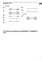
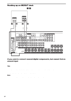
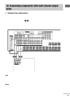
Getting Started 1: Check how to hookup your components Steps 1a through 1c beginning on page 8 describe how to hook up your components to this receiver. Before you begin, refer to "Connectable components" below for the pages which describe how to connect each component. After hooking up all your components, proceed to "2: Connecting the antennas" (page 15). Connectable components Component to be connected DVD player With digital audio outputa) With multi-channel audio outputb) With analog audio output onlyc) TV monitor With component video inputd) With S-Video or composite video input only Satellite tuner With digital audio outputa) With analog audio output onlyc) CD/Super Audio CD player With multi-channel audio outputb) With analog audio output onlyc) MD/DAT deck With digital audio outputa) With analog audio output onlyc) Tape deck, Analog disc turntable Multi-channel decoder VCR, video camera, video game, etc. Page 8-9 11-12 8-9 9 or 12 14 8-9 8-9 11 13 10 13 13 11 14 a) Model with a DIGITAL OPTICAL OUTPUT or DIGITAL COAXIAL OUTPUT jack, etc. b) Model with MULTI CH OUTPUT jacks, etc. This connection is used to output the audio decoded by the component's internal multi-channel decoder through this receiver. c) Model equipped only with AUDIO OUT L/R jacks, etc. d) Model with component video (Y, PB/CB/B-Y, PR/CR/R-Y) input jacks. 6GB
-
 1
1 -
 2
2 -
 3
3 -
 4
4 -
 5
5 -
 6
6 -
 7
7 -
 8
8 -
 9
9 -
 10
10 -
 11
11 -
 12
12 -
13
-
14
-
15
-
16
-
17
-
18
-
19
-
20
-
21
-
22
-
23
-
24
-
25
-
26
-
27
-
28
-
29
-
30
-
31
-
32
-
33
-
34
-
35
-
36
-
37
-
38
-
39
-
40
-
41
-
42
-
43
-
44
-
45
-
46
-
47
-
48
-
49
-
50
-
51
-
52
-
53
-
54
-
55
-
56
-
57
-
58
-
59
-
60
 |
 |
