Sony STR-DE675 Operating Instructions - Page 12
CONTROL A1, hookup, AUX AUDIO IN hookup, Setting the VOLTAGE SELECTOR Models of, area code E2, E3 - phono
 |
View all Sony STR-DE675 manuals
Add to My Manuals
Save this manual to your list of manuals |
Page 12 highlights
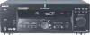
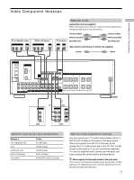
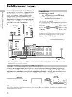
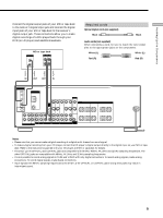
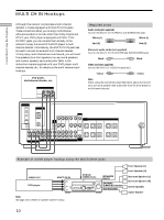
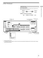
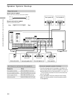
Hooking Up the Components Other Hookups CONTROL A1 hookup • If you have a CONTROL A1 compatible Sony CD player, tape deck, or MD deck Use a CONTROL A1 cord (not supplied) to connect the CONTROL A1 jack on the CD player, tape deck, or MD deck to the CONTROL A1 jack on the receiver. Refer "CONTROL-A1 Control System" on page 45 and the operating instructions supplied with your CD player, tape deck, or MD deck for details. Note If you make CONTROL A1 connections from the receiver to an MD deck that is also connected to a computer, do not operate the receiver while using the "Sony MD Editor" software. This may cause a malfunction. • If you have a Sony CD changer with a COMMAND MODE selector If your CD changer's COMMAND MODE selector can be set to CD 1, CD 2, or CD 3, be sure to set the command mode to "CD 1" and connect the changer to the CD jacks on the receiver. If, however, you have a Sony CD changer with VIDEO OUT jacks, set the command mode to "CD 2" and connect the changer to the VIDEO IN jacks on the receiver. AUX AUDIO IN hookup • If you have an individual audio component (except PHONO) Use the audio cords to connect the LINE OUT jacks on the CD player, tape deck, or MD deck to the AUX AUDIO IN jack on the receiver so that you can listen to stereo sources in surround sound. Setting the VOLTAGE SELECTOR (Models of area code E2, E3 only) Check that the voltage selector on the rear panel of the player is set to the local power line voltage. If not, set the selector to the correct position using a screwdriver before connecting the AC power cord to a wall outlet. 120 V 240 V 220 V Connecting the AC power cord Before connecting the AC power cord of this receiver to a wall outlet: • Connect the speaker system to the receiver (see page 14). Connect the AC power cord(s) of your audio/video components to a wall outlet. If you connect other audio/video components to the AC OUTLET(s) on the receiver, the receiver will supply power to the connected component(s), allowing you to turn the whole system on or off when you turn the receiver on or off. (except models of area code CN) Caution Make sure that the total power consumption of the component(s) connected to the receiver 's AC OUTLET(s) does not exceed the wattage stated on the rear panel. Do not connect high-wattage electrical home appliances such as electric irons, fans, or TVs to this outlet. (except models of area code CN) Note If the AC power cord is disconnected for about one week, the receiver 's entire memory will be cleared and the demonstration will start. 12
-
 1
1 -
2
-
3
-
4
-
5
-
6
-
 7
7 -
 8
8 -
 9
9 -
 10
10 -
 11
11 -
 12
12 -
 13
13 -
 14
14 -
 15
15 -
 16
16 -
 17
17 -
18
-
19
-
20
-
21
-
22
-
23
-
24
-
25
-
26
-
27
-
28
-
29
-
30
-
31
-
32
-
33
-
34
-
35
-
36
-
37
-
38
-
39
-
40
-
41
-
42
-
43
-
44
-
45
-
46
-
47
-
48
-
49
-
50
-
51
-
52
-
53
-
54
-
55
-
56
 |
 |