Sony STR-DE695 Operating Instructions - Page 13
Other hookups - digital audio video control center
 |
View all Sony STR-DE695 manuals
Add to My Manuals
Save this manual to your list of manuals |
Page 13 highlights
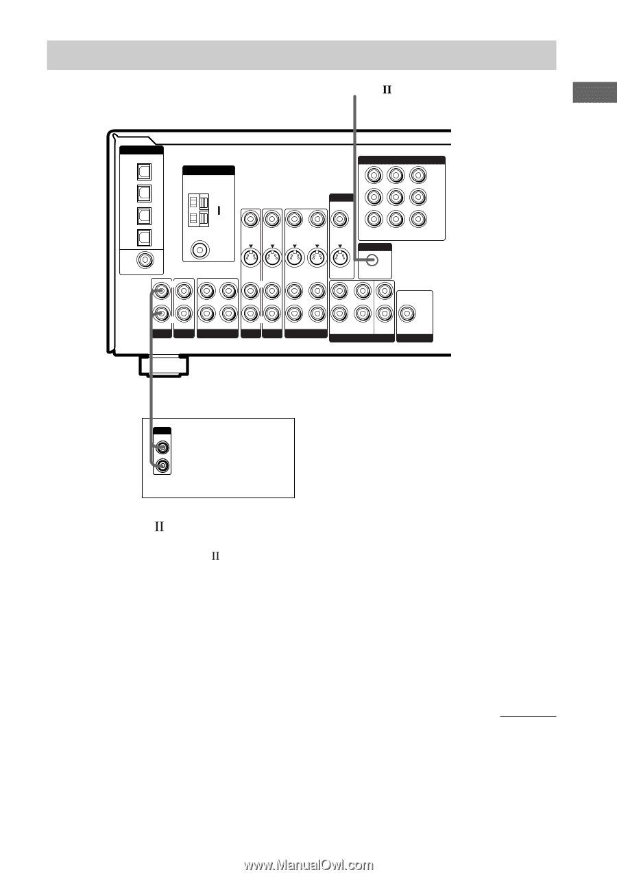
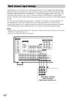
Hooking Up the Components Other hookups CONTROL A1 I DIGITAL OPTICAL VIDEO 2 IN MD/ TAPE IN MD/ TAPE OUT CD/ SACD IN DVD IN COAXIAL L ANTENNA COMPONENT VIDEO Y MONITOR PB/B-Y AM y FM 75Ω COAXIAL VIDEO IN VIDEO IN VIDEO OUT VIDEO IN VIDEO OUT DVD VIDEO 2 IN IN CTRL A1 II PR/R-Y MONITOR OUT S-VIDEO S-VIDEO S-VIDEO S-VIDEO S-VIDEO IN IN OUT IN OUT L L L L R R IN IN OUT IN AUX CD/SACD MD/TAPE R R AUDIO IN AUDIO IN AUDIO OUT AUDIO IN DVD VIDEO 2 VIDEO 1 CENTER R SUB FRONT SURROUND WOOFER MULTI CH IN SUB WOOFER PRE OUT ç IN A OUTPUT LINE L R CD player, tape deck, MD deck, etc. CONTROL A1 hookup • If you have a CONTROL A1 compatible Sony CD player, Super Audio CD player, tape deck or MD deck Use a monaural mini-plug cord (not supplied) to connect the CONTROL A1II jack on the CD player, Super Audio CD player, tape deck or MD deck to the CTRL A1II jack on the receiver. Refer to "CONTROL A1II control system" on page 40 and the operating instructions supplied with your CD player, Super Audio CD player, tape deck or MD deck for details. Note If you make CONTROL A1II connections from the receiver to an MD deck that is also connected to a computer, do not operate the receiver while using the "Sony MD Editor" software. This may cause a malfunction. • If you have a Sony CD changer with a COMMAND MODE selector If your CD changer's COMMAND MODE selector can be set to CD 1, CD 2, or CD 3, be sure to set the command mode to "CD 1" and connect the changer to the CD jacks on the receiver. However, if you have a Sony CD changer with VIDEO OUT jacks, set the command mode to "CD 2" and connect the changer to the VIDEO 2 jacks on the receiver. continued 13US
-
 1
1 -
2
-
3
-
4
-
5
-
6
-
7
-
 8
8 -
 9
9 -
 10
10 -
 11
11 -
 12
12 -
 13
13 -
 14
14 -
 15
15 -
 16
16 -
 17
17 -
 18
18 -
19
-
20
-
21
-
22
-
23
-
24
-
25
-
26
-
27
-
28
-
29
-
30
-
31
-
32
-
33
-
34
-
35
-
36
-
37
-
38
-
39
-
40
-
41
-
42
-
43
-
44
-
45
-
46
-
47
-
48
-
49
-
50
-
51
-
52
-
53
-
54
-
55
-
56
-
57
-
58
-
59
-
60
 |
 |