Sony STR-K850P Operating Instructions - Page 9
Video component hookups - no sound
 |
View all Sony STR-K850P manuals
Add to My Manuals
Save this manual to your list of manuals |
Page 9 highlights
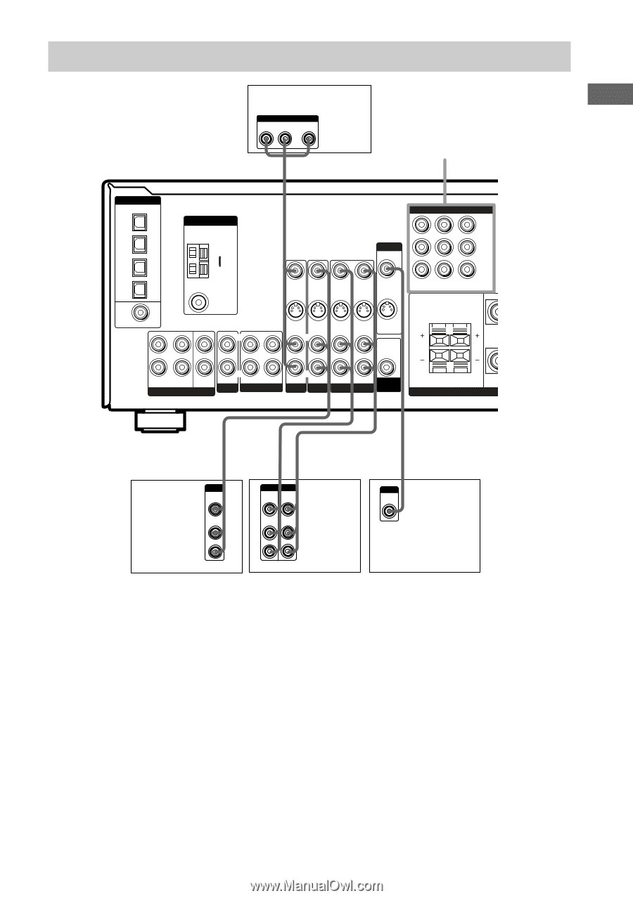
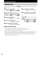
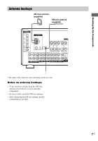
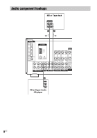
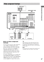
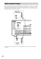
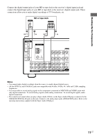
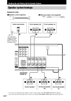
Hooking Up the Components Ç Ç Video component hookups DVD player OUTPUT AUDIO OUT R L VIDEO OUT B COMPONENT VIDEO H DIGITAL OPTICAL VIDEO 2 IN MD/ TAPE IN MD/ TAPE OUT CD/ SACD IN DVD IN COAXIAL L ANTENNA AM y FM 75Ω COAXIAL L CENTER MONITOR VIDEO IN VIDEO IN VIDEO OUT VIDEO IN VIDEO OUT S-VIDEO S-VIDEO IN IN L S-VIDEO S-VIDEO OUT IN L S-VIDEO OUT AUDIO OUT R R SUB FRONT SURROUND WOOFER MULTI CH IN IN CD/SACD OUT IN MD/TAPE R R AUDIO IN AUDIO IN AUDIO OUT AUDIO IN SUB DVD VIDEO 2 VIDEO 1 WOOFER COMPONENT VIDEO Y PB/B-Y PR/R-Y DVD VIDEO 2 MONITOR IN IN OUT RL R RL FRONT B SPE IN B OUTPUT VIDEO OUT Satellite tuner or VCR AUDIO OUT L R Ç OUT IN B B INPUT OUTPUT VIDEO VIDEO IN OUT AUDIO AUDIO IN OUT L R VCR C INPUT VIDEO IN TV monitor Note on video component hookups You can connect your TV's audio output jacks to the VIDEO 2 AUDIO IN jacks on the receiver and apply sound effects to the audio from the TV. In this case, do not connect the TV's video output jack to the VIDEO 2 VIDEO IN jack on the receiver. If you are connecting a separate satellite tuner, connect both the audio and video output jacks to the receiver as shown above. If you have a DVD player, TV or satellite tuner with COMPONENT VIDEO (Y, B-Y, R-Y) output jacks and a monitor with COMPONENT VIDEO input jacks, use a component video cord (not supplied) to connect to the receiver. Tip When using the S-video jacks instead of the video jacks, your monitor must also be connected via an S-video jack. S-video signals are on a separate bus from the video signals and will not be output through the video jacks. Note On this receiver, the component video signals are not compatible with S-video signals or video signals. 9US
-
 1
1 -
2
-
3
-
 4
4 -
 5
5 -
 6
6 -
 7
7 -
 8
8 -
 9
9 -
 10
10 -
 11
11 -
 12
12 -
 13
13 -
 14
14 -
15
-
16
-
17
-
18
-
19
-
20
-
21
-
22
-
23
-
24
-
25
-
26
-
27
-
28
-
29
-
30
-
31
-
32
-
33
-
34
-
35
-
36
-
37
-
38
-
39
-
40
-
41
-
42
-
43
-
44
-
45
-
46
-
47
-
48
-
49
-
50
-
51
-
52
 |
 |