Sony WX-4500X Installation/Connections Instructions - Page 1
Sony WX-4500X - Changer Control Audio Master Manual
 |
View all Sony WX-4500X manuals
Add to My Manuals
Save this manual to your list of manuals |
Page 1 highlights
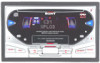
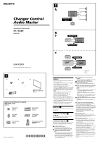
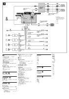
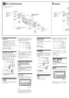
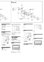
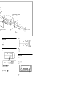
Changer Control Audio Master Installation/Connections 2 A SUBWOOFER OUT (MONO) B BUS AUDIO IN BUS CONTROL IN WX-4500X Sony Corporation © 2001 Printed in Japan 1 1 2 3 × 6 4 × 6 For NISSAN cars only Equipment used in illustrations (not supplied Front speaker Rear speaker Active subwoofer Power amplifier CD/MD changer Rotary commander RM-X4S *I-3-229-007-11* (1) BUS AUDIO IN Source selector BUS CONTROL IN * not supplied Cautions • This unit is designed for negative ground 12 V DC operation only. • Do not get the wires under a screw, or caught in moving parts (e.g. seat railing). • Before making connections, turn the car ignition off to avoid short circuits. • Connect the yellow and red power input leads only after all other leads have been connected. • Run all ground wires to a common ground point. • Be sure to insulate any loose unconnected wires with electrical tape for safety. • The use of optical instruments with this product will increase eye hazard. Notes on the power supply cord (yellow) • When connecting this unit in combination with other stereo components, the connected car circuit's rating must be higher than the sum of each component's fuse. • When no car circuits are rated high enough, connect the unit directly to the battery. Parts Iist (1) The numbers in the list are keyed to those in the instructions. Connection example (2) Tip (2-B- ) For connecting two or more changers, the source selector XA-C30 (optional) is necessary. Connection diagram (3) When insert the each connector, be sure to insert it securely, as vibration through driving may cause a poor connection. 1 To a metal surface of the car First connect the black ground lead, then connect the yellow and red power input leads. 2 To the power antenna control lead or power supply lead of antenna booster amplifier Notes • It is not necessary to connect this lead if there is no power antenna or antenna booster, or with a manually-operated telescopic antenna. • When your car has a built-in FM/AM antenna in the rear/side glass, see "Notes on the control and power supply leads." 3 To AMP REMOTE IN of an optional power amplifier This connection is only for amplifiers. Connecting any other system may damage the unit. 4 To the interface cable of a car telephone 5 To a car's illumination feed Be sure to connect the black ground lead to it first. 6 To the +12 V power terminal which is energized in the accessory position of the ignition key switch Notes • If there is no accessory position, connect to the +12 V power (battery) terminal which is energised at all times. Be sure to connect the black ground lead to it first. • When your car has a built-in FM/AM antenna in the rear/side glass, see "Notes on the control and power supply leads." 7 To the +12 V power terminal which is energised at all times Be sure to connect the black ground lead to it first. Notes on the control and power supply leads • The power antenna control lead (blue) supplies +12 V DC when you turn on the tuner. • When your car has built-in FM/AM antenna in the rear/side glass, connect the power antenna control lead (blue) or the accessory power input lead (red) to the power terminal of the existing antenna booster. For details, consult your dealer. • A power antenna without relay box cannot be used with this unit. Memory hold connection When the yellow power input lead is connected, power will always be supplied to the memory circuit even when the ignition key is turned off. Notes on speaker connection • Before connecting the speakers, turn the unit off. • Use speakers with an impedance of 4 to 8 ohms, and with adequate power handling capacities to avoid its damage. • Do not connect the speaker terminals to the car chassis, or connect the terminals of the right speakers with those of the left speaker. • Do not connect the ground lead of this unit to the negative (-) terminal of the speaker. • Do not attempt to connect the speakers in parallel. • Connect only passive speakers. Connecting active speakers (with built-in amplifiers) to the speaker terminals may damage the unit. • To avoid a malfunction, do not use the built-in speaker wires installed in your car if the unit shares a common negative (-) lead for the right and left speakers. • Do not connect the unit's speaker cords to each other.
-
 1
1 -
 2
2 -
 3
3 -
 4
4 -
 5
5
 |
 |