Sony XCES30CE User Manual (XCES_Series_User_Guide) - Page 7
Location Of Parts And Operation, Xc-es50/50ce
 |
View all Sony XCES30CE manuals
Add to My Manuals
Save this manual to your list of manuals |
Page 7 highlights
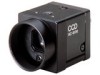
LOCATION OF PARTS AND OPERATION XC-E series XC-ES50/50CE . XC-ES30/30CE XC-EI50/50CE . XC-EI30/30CE 2 4 1 23 3 4 7 1 Lens mount section (C mount) A commercial C-mount lens as well as a Sony standard lens can be used. 2 Camera mounting reference hole (top) These screw holes are positionned with high precision related to CCD sensor. 3 Camera mounting reference hole/Screw hole for tripod adaptor mounting (bottom) 4 12-pin multi-connector DC IN/HD/VD (DC power/sync signal input) VIDEO OUT terminal 5 75 Ω termination selector switch 6 HD/VD input-output selector switch 8 56 412-pin multi-connector Pin No. External HD/VD synchronization Internal HD/VD synchronization 1 GND GND 2 +12 V +12 V 3 GND GND 4 VIDEO output VIDEO output 5 GND GND 6 External HD input Internal HD output 7 *1 External VD input Internal VD output 8 GND GND 9 - - 10 *2 WEN output 11 TRIG input *2 WEN output TRIG input 12 GND GND *1: An input VD signal is required when the restart/reset mode is used. *2: A WEN output signal is valid only in the external trigger shutter mode. • Factory-setting mode of rear panel Corresponding No. Switch Factory-setting mode 5 75 Ω termination selector switch ON 6 HD/VD input-output selector switch EXT 7 Shutter speed/mode setting DIP switch Switches 1 to 4: Select the shutter speed. OFF Switch 5: Selects the frame or field integration. FRAME Switches 6 to 8: Select the trigger shutter mode. Normal Switch 9: Selects correction on/off. OFF Switch 0: Selects the gain. 8 Volume control switch Manual Mechanical center 7 Shutter speed/mode setting DIP switch Switches 1 to 4: Select the shutter speed. Switch 5: Selects the frame or field integration. Switches 6 to 8: Select the trigger shutter mode. Switch 9: Selects γ correction on/off. Switch 0: Selects the gain. 8 Volume control switch This switch can be changed in the range of Switch 0 to 18 dB when the GAIN switch is set to "M". * During factory setting, this switch is adjusted to the mechanical center. n When setting DIP switch 5 to the frame integration, set the volume control switch 8 to the MAX side from the mechanical center (because of CCD characteristics). 5
-
 1
1 -
 2
2 -
 3
3 -
 4
4 -
 5
5 -
 6
6 -
 7
7 -
 8
8 -
 9
9 -
 10
10 -
 11
11 -
 12
12 -
13
-
14
-
15
-
16
-
17
-
18
-
19
-
20
-
21
-
22
-
23
-
24
-
25
-
26
-
27
-
28
-
29
-
30
-
31
-
32
-
33
-
34
-
35
-
36
-
37
-
38
-
39
 |
 |
