Sony XCST70 Product Manual (Black & White Analog Camera) - Page 1

Sony XCST70 Manual

Page 1 highlights

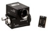
3-867-357-04 (1) CCD Black-and-White Video Camera Module Operating Instructions XC-ST70/ ST70CE XC-ST50/ ST50CE XC-ST30/ ST30CE Sony Corporation  1999 Printed in Japan ͋Γ·͢ɻ D C ·ͨɺ1೥ʹ1 Owner's Record The model and serial numbers are located on the bottom. Record the serial number in the space provided below. Refer to these numbers whenever you call upon your Sony dealer regarding this product. Model No Serial No WARNING To prevent fire or shock hazard, do not expose the unit to rain or moisture. This symbol is intended to alert the user to the presence of important operating and maintenance (servicing) instructions in the literature accompanying the appliance. For the customers in the USA This equipment has been tested and found to comply with the limits for a Class A digital device, pursuant to Part 15 of the FCC Rules. These limits are designed to provide reasonable protection against harmful interference when the equipment is operated in a commercial environment. This equipment generates, uses, and can radiate radio frequency energy and, if not installed and used in accordance with the instruction manual, may cause harmful interference to radio communications. Operation of this equipment in a residential area is likely to cause harmful interference in which case the user will be required to correct the interference at his own expense. You are cautioned that any changes or modifications not expressly approved in this manual could void your authority to operate this equipment. The shielded interface cable recommended in this manual must be used with this equipment in order to comply with the limits for a digital device pursuant to Subpart B of Part 15 of FCC Rules. For the customers in Europe WARNING This is a Class A product. In a domestic environment this product may cause radio interference in which case the user may be required to take adequate measures. Pour les utilisateurs en Europe AVERTISSEMENT Il s'agit d'un produit de Classe A. Dans un environnement domestique, cet appareil peut provoquer des interférences radio, dans ce cas l'utilisateur peut être amené à prendre des measures appropriées. Für Kunden in Europa Warnung Dies ist eine Einrichtung, weiche die Funk-Entstörung nach Klasse A besitzt. Diese Einrichtung kann im Wohnbereich Funkstörungen verursachen; in diesem Fall kann vom Betreiber verlangt werden, angemessene Maßnahmen durchzuführen und dafür anfzukommen. Für Kunden in Deutschland Dieses ist ein Gerät der Klasse A. Es ist nur für den Einsatz in einem Industriegebiet bestimmt. A Χϝϥ / Camera GND2 1 2 3 4 GND1 3 GND3 B 1 2 3 4 5 C 1 1 XC-ST series 3 4 DC-700 2 3 WEN HD VIDEO CAMERA 1 AC IN 12 2 4 2 5 TRIG VD/SYNC 5 8 6 7 9 6 D 1 2 ਤA 1 3 2 4 Ϟχλʔ DC+12V ͍͞ɻ ์೤ 0ʙ40ˆͰ͢ɻ ͓खೖΕ ֓ཁ XC-ST CCDʢCharge Coupled DeviceʣΛ࠾༻ ߴը࣭ 768ʷ494ըૉͷCCD 75 HDɺVD HDɺVD VSʢVideoɺSyncʣ৴߸ɿVS HDɺVD VS HD৴߸ͱVD 12ϐϯ FL 1/125ʙ 1/10000 CCD ৽EIAJ12 WEN ߏ੒ ਤB XC-ST 1 CCD 2 CCXC-12P02Nʢ2mʣ/05Nʢ5mʣ/10Nʢ10mʣ/ 25Nʢ25m) DC IN/SYNC 3 C VCL-08YM/12YM/16Y-M/25Y-M/50Y-M 4 DC-700 AC 5 VCT-ST70I ઀ଓྫ ਤC DC-700 DC-700 DC-700 DC-700 1 Ϟχλʔ 2 C VCL-16Y-MͳͲʣ 3 75 4 CCXC-12P05NͳͲʣ 5 TRIG 6 1 DC IN/SYNC୺ࢠ 2 VIDEO 1୺ࢠ΁ 3 CAMERA୺ࢠ΁ 4 ʙAC IN୺ࢠ΁ 5 AC 6 HD୺ࢠ΁ 7 VD/SYNC୺ࢠ΁ 8 HDग़ྗ 9 VDग़ྗ ਤD 1 CϚ΢ϯτ) C ͝஫ҙ C 7mmҎ 1 2 7mmҎԼ 2 3 ఈ໘ͷ4 4 VCT-ST70I English When installing the camera Fig. A When you install the camera with various peripheral devices and if the devices have different ground electric potential, ground only one device. In case there is an ground electric potential difference, the camera may be damaged. 1 Power supply unit 2 Abnormal electricity 3 Ground electric potencial difference 4 Monitor Notes on Operation Power supply The camera operates on 12V DC. Use a stable power source free from ripple or noise. Foreign bodies Be careful not to spill liquids, or drop any flammable or metal objects in the camera body. Heat radiation Do not wrap the camera in cloth or other material while in operation. There is a danger of overheating. Locations for operation and storage Avoid operation or storage in the following places. • Extremely hot or cold locations. Recommended temperature range is 0°C to 40°C. (32°F to 104°F) • Humid or dusty locations • Locations exposed to rain • Locations subject to strong vibration • Near generators of strong electromagnetic radiation such as TV or radio transmitters. Care Use a blower to remove dust from the surface of the lens or optical filter. Clean the exterior with a soft, dry cloth. If the camera is very grimy, apply a cloth soaked in a mild detergent then wipe with a dry cloth. Do not apply organic solvents such as alcohol which may damage the finish. Overview Before operating the unit, please read this manual thoroughly and retain for future reference. The XC-ST series is a monochrome video camera module using an interline transfer CCD (Charge Coupled Device) solid state image sensor. High image quality The interline transfer CCD provides a high-resolution image with 768 × 494 pixels (XC-ST70/ST50/ST30) or 752 × 582 pixels (XC-ST70CE/ST50CE/ ST30CE). Various mode settings Rear panel switches allow the following mode settings. • Gain: Auto/Fixed/Manual • γ compensation • Synchronized input/output • Potential accumulation: FLAME/FIELD • 75Ω termination • Trigger pulse polarity: +/- • Shutter speed: Normal/Trigger shutter External synchronization HD (horizontal drive), VD (vertical drive) signals: The camera module automatically determines whether to operate in interlace or noninterlace mode from the HD and VD signals input for external synchronization. VS (Video/Sync) signals: External synchronization with a video or composite sync signal. (The unit switches automatically between HD/VD and VS synchronization.) Internal sync signal output You can output the HD and VD signals from the 12-pin connector by changing the rear panel switch. Electronic shutter function Shutter speed can be selected from a wide range (1/125 to 1/10000 sec.) or in flickerless (FL) mode. Body fixing These mounting screw holes are provided in the reference plane on the lower surface of the body, allowing mounting with the absolute minimum deviation of the optical axis. The connector complies with the new EIAJ 12-pin pin assignment The new pin arrangement allows the connector to accept a trigger pulse and a WEN signal. System Components Fig. B The CCD Black-and-White Video Camera Module XC-ST series system comprises the following optional products (available separately). 1 CCD Black-and-White Video Camera Module This is a small-size, high-resolution, monochrome video camera module using an interline transfer CCD image sensor. 2 CCXC-12P02N (2m, 6.6ft)/05N (5m, 16.4ft)/10N (10m, 32.8ft)/25N (25m, 82ft) camera cable This is attached to the DC IN/SYNC connector of the camera module and is used for power supply, transmission of video signals, and exchange of sync signals. 3 C-mount lens Recommended lens: VCL-08YM/12YM/16Y-M/25Y-M/50Y-M 4 DC-700/700CE camera adaptor This is connected to the camera module to enable power supply from ordinary AC power source, and also handles transmission of video signals from the camera module and exchange of sync signals between the camera module and an external sync signal generator. 5 VCT-ST70I tripod adaptor This attaches to the bottom of the camera module to fix the camera module to a tripod. Connection example Fig. C Connecting DC-700/700CE (not supplied) Connect the camera module to the power via the camera adaptor DC-700/ 700CE. For details on the camera adaptor DC-700/700CE, see the DC-700/700CE Instruction Manual. 1 Monitor 1 DC IN/SYNC connector 2 C-mount lens (e.g. VCL-16Y-M) 2 To VIDEO 1 connector 3 75-ohm coaxial cable etc. 3 To CAMERA connector 4 Camera cable (e.g. CCXC-12P05N) 4 To AC IN connector 5 TRIG generator, Image processor 5 To AC power source 6 Sync. signal generator 6 To HD connector 7 To VD/SYNC connector 8 HD output 9 VD output Location and Function of Parts and Operation Front/Top/Bottom Fig. D 1 Lens mount (C-mount) Attach any C-mount lens or other optical equipment. Note The lens must not project more than 7 mm (9/32 inch) from the lens mount. 1 Lens mount face 2 7 mm (9/32 inch) or less 2 Reference hole (Top) 3 Reference hole/Tripod screw holes (bottom) These precision screw holes are for locking the camera module. Locking the camera module into these holes secures the optical axis alignment. For details on dimensions, etc., see "About the User's Guide" on the lower right of the back side. You can install the camera on a tripod. To install on a tripod, you will need to install a tripod adaptor VCT-ST70I to the camera on the reference holes of the bottom of the camera. 3 2 1

  • 1
  • 2

3-867-357-
04
(1)
白黒ビデオカメラモジュール
CCD Black-and-White
Video Camera Module
Sony Corporation
1999
Printed in Japan
XC-ST70/ST70CE
XC-ST50/ST50CE
XC-ST30/ST30CE
安全のために
ソニー製品は安全に充分に配慮して設計されています。しかし、まちがった
使いかたをすると、火災や感電などにより死亡や大けがなど人身事故につな
がることがあり、危険です。
事故を防ぐために次のことを必ずお守りください。
安全のための注意事項を守る。
長期間、安全にお使いいただくために、定期点検をすることをおすすめ
します。点検の内容や費用については、お買い上げ店にご相談ください。
故障したら使わずに、お買い上げ店にご連絡ください。
取扱説明書
Operating Instructions
お買い上げいただきありがとうございます。
電気製品は、安全のための注意事項を守らないと、けがをし
たり周辺の物品に損害を与えることがあります。
この取扱説明書には、事故を防ぐための重要な注意事項と製品の取り扱い
かたを示してあります。この取扱説明書をよくお読みのうえ、製品を安全
にお使いください。お読みになったあとは、いつでも見られるところに必
ず保管してください。
行為を禁止する記号
行為を指示する記号
警告表示の意味
この取扱説明書および製品では、次のよ
うな表示をしています。表示の内容をよ
く理解してから本文をお読みください。
この表示の注意事項を守らないと、
火災
やその他の事故により
けが
をしたり周
辺の物品に
損害
を与えたりすることが
あります。
下記の注意事項を守らないと、
けが
をしたり周辺の物品に
損害
を与えることがあります。
内部に水や異物を入れない
水や異物が入ると、火災の原因となります。
万一、水や異物が入ったときは、すぐに本機が接続され
ている電源供給機器の電源を切り、
DC
電源ケーブルや
接続ケーブルを抜いて、お買い上げ店にご相談くださ
い。
分解しない、改造しない
分解や改造をすると、火災やけがの原因となります。
点検および修理は、お買い上げ店にご依頼ください。
カメラケーブルを傷つけない
カメラケーブルを傷つけると、火災や故障の原因となる
ことがあります。次の項目をお守りください。
設置時に、製品と壁やラック、棚などの間に、はさみ込
まない。
カメラケーブルを加工したり、傷つけたりしない。
重いものをのせたり、引っ張ったりしない。
熱器具に近づけたり、加熱したりしない。
カメラケーブルを抜くときは、必ずプラグを持って抜
く。
芯線の露出や断線などでカメラケーブルが傷んだら、お
買い上げ店に交換をご依頼ください。そのまま使用する
と、火災の原因となります。
設置は確実に
設置については、必ずお買い上げ店にご相談ください。
壁面や天井などへの設置は、本機と取り付け金具を含む
重量に充分耐えられる強度があることをお確かめくだ
さい。充分な強度がないと、落下して、大けがの原因とな
ります。
また、
1
年に
1
度は、取り付けがゆるんでいないことを点
検してください。
指定された電源を使う
この取扱説明書に記されている電源供給機器(カメラア
ダプターなど)でお使いください。規定外の電源でのご
使用は、火災の原因となることがあります。
指定されたカメラケーブル、接続ケーブルを使う
この取扱説明書に記されているカメラケーブル、接続
ケーブルを使わないと、火災や故障の原因となることが
あります。
Owner’s Record
The model and serial numbers are located on the bottom.
Record the serial number in the space provided below.
Refer to these numbers whenever you call upon your Sony
dealer regarding this product.
Model No. _____________
Serial No. ______________
For the customers in the USA
This equipment has been tested and found to comply with the limits
for a Class A digital device, pursuant to Part 15 of the FCC Rules.
These limits are designed to provide reasonable protection against
harmful interference when the equipment is operated in a
commercial environment. This equipment generates, uses, and can
radiate radio frequency energy and, if not installed and used in
accordance with the instruction manual, may cause harmful
interference to radio communications. Operation of this equipment
in a residential area is likely to cause harmful interference in which
case the user will be required to correct the interference at his own
expense.
You are cautioned that any changes or modifications not expressly
approved in this manual could void your authority to operate this
equipment.
The shielded interface cable recommended in this manual must be
used with this equipment in order to comply with the limits for a
digital device pursuant to Subpart B of Part 15 of FCC Rules.
For the customers in Europe
WARNING
This is a Class A product. In a domestic environment this product
may cause radio interference in which case the user may be
required to take adequate measures.
Pour les utilisateurs en Europe
AVERTISSEMENT
Il s’agit d’un produit de Classe A. Dans un environnement
domestique, cet appareil peut provoquer des interférences radio,
dans ce cas l’utilisateur peut être amené à prendre des measures
appropriées.
Für Kunden in Europa
Warnung
Dies ist eine Einrichtung, weiche die Funk-Entstörung nach Klasse
A besitzt. Diese Einrichtung kann im Wohnbereich Funkstörungen
verursachen; in diesem Fall kann vom Betreiber verlangt werden,
angemessene Maßnahmen durchzuführen und dafür
anfzukommen.
Für Kunden in Deutschland
Dieses ist ein Gerät der Klasse A. Es ist nur für den Einsatz in
einem Industriegebiet bestimmt.
This symbol is intended to alert the user to
the presence of important operating and
maintenance (servicing) instructions in the
literature accompanying the appliance.
A
B
日本語
English
カメラ設置上のご注意
A
カメラ設置の際は、周辺機器を含めてカメラに接続されている各機器間で接
地電位の差が生じないようにしてください。接地電位差により故障の原因と
なる場合があります。設置の都合により電位差を生ずる場合は、機器の内い
ずれかひとつの機器だけを接地するようにしてください。
1
電源
2
異常電流
3
接地電位差
4
モニター
使用上のご注意
電源について
DC+12V
で動作します。リップル、ノイズのない安定した電源をお使いくだ
さい。
放熱
内部の温度上昇を避けるため、動作中は布などで包まないでください。
使用・保管場所
次のような場所での使用および保管はお避けください。
極端に暑い所や寒い所。適正使用温度は
0
40
℃です。
湿気、ほこりの多い所。
雨にあたる所。
激しい振動のある所。
強力な電波を発生するテレビ、ラジオの送信所の近く。
お手入れ
レンズや光学フィルターの表面に付着したごみやほこりは、ブロアーで払っ
てください。外装の汚れは、乾いた柔らかい布でふきとります。ひどい汚れ
は、中性洗剤溶液を少し含ませた布でふきとった後、からぶきします。アル
コール、ベンジンなどは、変質したり塗料がはげることがありますので、使
用しないでください。
概要
XC-ST
シリーズは固体撮像素子
CCD
Charge Coupled Device
)を採用
した白黒ビデオカメラモジュールです。
高画質
768
×
494
画素の
CCD
により、きめ細かな画像を再現します。
多様なモード設定
リアパネルのスイッチの切り換えにより、以下のモード設定が可能です。
ゲイン
:
自動調整/固定/手動調整
γ補正
同期入出力
電荷蓄積
:
フレーム蓄積/フィールド蓄積
75
Ω終端
トリガーパルス極性
:
+/-
シャッタースピード
:
ノーマル/トリガーシャッター
外部同期
HD
VD
信号:
入力された
HD
VD
信号から、インターレース方式かノンイ
ンターレース方式かを自動的に識別し、その方式に応じて外部同期で動作
します。
VS
Video
Sync
)信号:
VS
信号(映像信号または複合同期信号)によ
り、外部同期で動作します。(
HD
VD
信号による同期方式と
VS
信号に
よる同期方式は、外部入力信号に応じて自動的に切り換わります。
)
内部同期信号出力
HD
信号と
VD
信号は、リヤパネルのスイッチを変更することにより、
12
ピン
コネクターから出力させることができます。
電子シャッター
FL
(フリッカーレス)モードと豊富なシャッタースピード(
1/125
1/10000
秒)の中から、撮影条件に合った速度が選べます。
筐体固定
筐体固定用のネジ穴が
CCD
の基準面に設けてあります。ここでカメラモ
ジュールを固定すれば、光軸のずれを最小限にとどめることができます。
EIAJ12
ピンコネクターピンアサイメント準拠
トリガーパルスや
WEN
信号を追加した、新しいピン配置になっています。
構成
B
白黒ビデオカメラモジュール
XC-ST
シリーズを中心としたシステムの構成品
目は、次のとおりです。(いずれも別売りです。
)
1
白黒ビデオカメラモジュール
CCD
を用いた、小型、高解像度の白黒カメラです。
2
カメラケーブル
CCXC-12P02N
2m
/05N
5m
/10N
10m
/
25N
25m)
カメラモジュール裏面の
DC IN/SYNC
端子に接続し、電力の供給や映像信
号の送出、同期信号の授受を行います。
3
C
マウントレンズ
推奨レンズ:
VCL-08YM/12YM/16Y-M/25Y-M/50Y-M
4
カメラアダプター
DC-700
AC
電源から電力を供給する場合に、カメラモジュールに接続して使用しま
す。映像信号の送出および同期信号の授受も行えます。
5
三脚アダプター
VCT-ST70I
三脚を使ってカメラモジュールを固定するとき、このアダプターをカメラモ
ジュールの底部に取り付けます。
接続例
C
DC-700
(別売)との接続例
カメラモジュールを、カメラアダプター
DC-700
を介して電源に接続しま
す。カメラアダプター
DC-700
の詳細については、
DC-700
の取扱説明書を
ご覧ください。
1
モニター
1
DC IN/SYNC
端子
2
C
マウントレンズ(
VCL-16Y-M
など)
2
VIDEO 1
端子へ
3
75
Ω同軸ケーブル
3
CAMERA
端子へ
4
カメラケーブル(
CCXC-12P05N
など)
4
AC IN
端子へ
5
TRIG
発生器、画像処理装置
5
AC
電源へ
6
同期信号発生器
6
HD
端子へ
7
VD/SYNC
端子へ
8
HD
出力
9
VD
出力
各部の名称と働き
前面/上面/底面
D
1
レンズマウント(
C
マウント
)
C
マウント式のレンズや光学機器を取り付けます。
ご注意
C
マウント式のレンズとして、レンズマウント面からの飛び出し量が
7mm
下のものを使用してください。
1
レンズマウント部
2
7mm
以下
2
カメラ固定用基準穴(上面)
3
カメラ固定用基準穴/三脚取り付け用ネジ穴(底面)
カメラモジュール固定用に高い精度で切られたネジ穴です。ここでカメラモ
ジュールを固定すると、光軸のずれを最小限にとどめることができます。
寸法など詳しくは裏面右下の「ユーザーズガイドについて」をご覧ください。
底面の
4
つのカメラ固定用基準穴は三脚アダプター取り付け用ネジ穴としても
使用できます。三脚を使うときは、この
4
つのネジ穴を使って三脚アダプター
VCT-ST70I
を取り付けます。
C
WARNING
To prevent fire or shock hazard, do not expose
the unit to rain or moisture.
D
1
2
GND2
GND1
GND3
3
3
4
1
2
3
1
2
3
4
5
カメラ
/
Camera
When installing the camera
Fig. A
When you install the camera with various peripheral devices and if the
devices have different ground electric potential, ground only one device. In
case there is an ground electric potential difference, the camera may be
damaged.
1
Power supply unit
2
Abnormal electricity
3
Ground electric potencial difference
4
Monitor
Notes on Operation
Power supply
The camera operates on 12V DC. Use a stable power source free from
ripple or noise.
Foreign bodies
Be careful not to spill liquids, or drop any flammable or metal objects in the
camera body.
Heat radiation
Do not wrap the camera in cloth or other material while in operation. There
is a danger of overheating.
Locations for operation and storage
Avoid operation or storage in the following places.
• Extremely hot or cold locations. Recommended temperature range is 0°C
to 40°C. (32°F to 104°F)
• Humid or dusty locations
• Locations exposed to rain
• Locations subject to strong vibration
• Near generators of strong electromagnetic radiation such as TV or radio
transmitters.
Care
Use a blower to remove dust from the surface of the lens or optical filter.
Clean the exterior with a soft, dry cloth.
If the camera is very grimy, apply a cloth soaked in a mild detergent then
wipe with a dry cloth. Do not apply organic solvents such as alcohol which
may damage the finish.
Overview
Before operating the unit, please read this manual thoroughly and retain for
future reference.
The XC-ST series is a monochrome video camera module using an interline
transfer CCD (Charge Coupled Device) solid state image sensor.
High image quality
The interline transfer CCD provides a high-resolution image with 768
×
494
pixels (XC-ST70/ST50/ST30) or 752
×
582 pixels (XC-ST70CE/ST50CE/
ST30CE).
Various mode settings
Rear panel switches allow the following mode settings.
• Gain: Auto/Fixed/Manual
γ
compensation
• Synchronized input/output
• Potential accumulation: FLAME/FIELD
• 75
termination
• Trigger pulse polarity: +/–
• Shutter speed: Normal/Trigger shutter
External synchronization
HD (horizontal drive), VD (vertical drive) signals:
The camera module
automatically determines whether to operate in interlace or noninterlace
mode from the HD and VD signals input for external synchronization.
VS (Video/Sync) signals:
External synchronization with a video or
composite sync signal. (The unit switches automatically between HD/VD
and VS synchronization.)
Internal sync signal output
You can output the HD and VD signals from the 12-pin connector by
changing the rear panel switch.
Electronic shutter function
Shutter speed can be selected from a wide range (1/125 to 1/10000 sec.) or
in flickerless (FL) mode.
Body fixing
These mounting screw holes are provided in the reference plane on the
lower surface of the body, allowing mounting with the absolute minimum
deviation of the optical axis.
The connector complies with the new EIAJ 12-pin pin
assignment
The new pin arrangement allows the connector to accept a trigger pulse and
a WEN signal.
System Components
Fig. B
The CCD Black-and-White Video Camera Module XC-ST series system
comprises the following optional products (available separately).
1
CCD Black-and-White Video Camera Module
This is a small-size, high-resolution, monochrome video camera module
using an interline transfer CCD image sensor.
2
CCXC-12P02N (2m, 6.6ft)/05N (5m, 16.4ft)/10N (10m, 32.8ft)/25N
(25m, 82ft) camera cable
This is attached to the DC IN/SYNC connector of the camera module and is
used for power supply, transmission of video signals, and exchange of sync
signals.
3
C-mount lens
Recommended lens: VCL-08YM/12YM/16Y-M/25Y-M/50Y-M
4
DC-700/700CE camera adaptor
This is connected to the camera module to enable power supply from
ordinary AC power source, and also handles transmission of video signals
from the camera module and exchange of sync signals between the camera
module and an external sync signal generator.
5
VCT-ST70I tripod adaptor
This attaches to the bottom of the camera module to fix the camera module
to a tripod.
Connection example
Fig. C
Connecting DC-700/700CE (not supplied)
Connect the camera module to the power via the camera adaptor DC-700/
700CE.
For details on the camera adaptor DC-700/700CE, see the DC-700/700CE
Instruction Manual.
1
Monitor
1
DC IN/SYNC connector
2
C-mount lens (e.g. VCL-16Y-M)
2
To VIDEO 1 connector
3
75-ohm coaxial cable etc.
3
To CAMERA connector
4
Camera cable (e.g. CCXC-12P05N)
4
To AC IN connector
5
TRIG generator, Image processor
5
To AC power source
6
Sync. signal generator
6
To HD connector
7
To VD/SYNC connector
8
HD output
9
VD output
Location and Function of Parts and Operation
Front/Top/Bottom
Fig. D
1
Lens mount (C-mount)
Attach any C-mount lens or other optical equipment.
Note
The lens must not project more than 7 mm (9/32 inch) from the lens mount.
1
Lens mount face
2
7 mm (9/32 inch) or less
2
Reference hole (Top)
3
Reference hole/Tripod screw holes (bottom)
These precision screw holes are for locking the camera module.
Locking
the camera module into these holes secures the optical axis alignment.
For details on dimensions, etc., see “About the User’s Guide” on the lower right of the
back side.
You can install the camera on a tripod. To install on a tripod, you will need
to install a tripod adaptor VCT-ST70I to the camera on the reference holes
of the bottom of the camera.
WEN
TRIG
HD
VD/SYNC
AC IN
1
1
2
2
CAMERA
VIDEO
1
2
2
3
4
1
5
6
7
9
8
6
5
4
3
DC-700
XC-ST series
1
2