Sony XCST70 Product Manual (Black & White Analog Camera) - Page 2

三脚の取り付け, 特有の現象, 主な仕様 - xc st70ce manual

Page 2 highlights

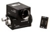
E qs 4 5 6 7 qa 8 0 9 1 2 3 F DIP DIP switch setting a Shutter speed unit: second) γϟολʔ OFF Shutter OFF 1/125 1/250 1/500 1/1000 1/2000 1/4000 1/10000 Flickerless* (EIA: 1/100 CCIR: 1/120) bit 1ʙ3 Flickerless setting (bits 1- 3): Arbitrary b Potential accumulation mode ϑϨʔϜ ஝ੵ FRAME ϑΟʔϧυ ஝ੵ FIELD c Restart reset/External trigger shutter mode switch ϊʔϚϧ* Normal* Ϧελʔτ Ϧηοτ Restart Reset Ϟʔυ2 Ϟʔυ1 External Trigger External Trigger Shutter mode 2 Shutter mode 1 bit 6, 7 Normal setting (bits 6 and 7): Arbitrary ‫ޙ‬໘ ਤE 4 HD/VD HD/VD INT HD/VD EXT EXTଆʹ 5 VIDEO OUT BNC‫)ܕ‬ 6 γ ิਖ਼ON/OFF ON OFFͰ͢ɻ 7 GAIN A F M FͰ͢ɻ 8 GAIN 7ͰM 9 DIPεΠον ਤFࢀর 1 bit 1ʙ4ʣ F-a 2 bit 5ʣ F-b 3 bit 6ʙ8ʣ F-c ͝஫ҙ F-cʹ bit 1ʙ4Λ͢΂ͯ0ͷ 0 75 OFF ONͰ͢ɻ qa TRIG qs DC IN/SYNCʢDC 12 CCXC-12P05N DCʴ12V VS·ͨ͸HD/VD ϐϯNo E-qs ϐϯ൪߸ 1 2 3 4 5 6 7 8 9 10 11 12 HD/VD Ξʔε DCʴ12V HD HD VD - - - - VD VS Ξʔε DCʴ12V - - VS VS ϐϯ൪߸ 1 2 3 4 5 6 7 8 9 10 11 12 DCʴ12V HD HD DCʴ12V HD HD VD - - WEN VD 1 Ξʔε 2 DCʴ12V 3 4 5 HD 6 VD 7 VD 8 - 9 - 10 - 11 - 12 VD VCT-ST70I 4 ͍ͩ͘͞ɻ ISO‫ ֨ن‬4ɿ4.5mmʶ0.2mm ASA‫ ֨ن‬4ɿ0.197Πϯν 4 ͝஫ҙ CCD CCD Γ·ͤΜɻ εϛΞ CCD ই CCD ඍখന఺ ͝஫ҙ ओͳ࢓༷ ࡱ૾ૉࢠ CCD CCD XC-ST70 2/3‫ܕ‬CCD XC-ST50 1/2‫ܕ‬CCD XC-ST30 1/3‫ܕ‬CCD 768ʷ494 43ըૉ 15.734kHzʶ1ˋ 14.318MHz EIAํࣜ XC-ST70: 11.6ʷ13.5Жm XC-ST50: 8.4ʷ9.8Жm XC-ST30: 6.35ʷ7.4Жm XC-ST70: 10.25ʷ8.5mm XC-ST50: 7.95ʷ6.45mm XC-ST30: 6.00ʷ4.96mm CϚ΢ϯτ 17.526mm SɺVS (SYNCϨϕϧɿ0.3Vp-pʶ6dB) HD/VD (HD/VDϨϕϧɿ2ʙ5Vp-p) ʶ1 Hδολʔ ʶ50nsecҎ಺ ૸ࠪํࣜ 525ຊ 2ɿ1 ө૾ग़ྗ 1.0Vp-p 75Њෆฏߧ 570TVຊ 485ຊɹ(2ɿ1 ‫౓ײ‬ XC-ST70/ST50: 400lxɺF8ɹ (Ѝิਖ਼ONɺ0dB) XC-ST30: 400lxɺF5.6 0.3lxɹ(ЍON) IR cut Filterͳ͠ F1.4ɺЍิਖ਼ON) ө૾SʗNൺ XC-ST70/ST50: 60dB XC-ST30: 56dB ήΠϯ Ѝ 1 115IREʶ10IRE 1/125ɺ1/250ɺ1/500ɺ1/1000ɺ1/2000ɺ 1/4000ɺ1/10000 ‫)͑׵‬ 1/4ʙ1/10000ඵ DCʴ12V (ൣғɿʴ10.5ʙ15V) ফඅిྗ XC-ST70: 2.1W XC-ST50: 2.0W XC-ST30: 1.9W ಈ࡞Թ౓ ʵ5ʙʴ45ˆ อଘԹ౓ ʵ30ʙʴ60ˆ ࢖༻࣪౓ 20ʙ80 อଘ࣪౓ 20ʙ95 ଱ৼಈੑ 10G (20Hzʙ200Hz) ଱িܸੑ 70G 44 (W)ʷ29 (H)ʷ57.5 (D)mm ॏྔ XC-ST70: 105g XC-ST50/30: 110g ෇ଐ඼ 1) 1) Rear Fig. E 4 HD/VD signal input/output switch Set the switch to INT to output the HD/VD signals from the camera module. Set the switch to EXT to input the HD/VD signals from an external unit. (Factory setting: EXT) 5 VIDEO OUT (Video signal output) connector (BNC) You can use this connector for video signal output from the camera module. 6 γ compensation ON/OFF switch Turn on this switch for γ compensation. (Factory setting: OFF) 7 GAIN switch This switch selects AGC (A), fixed gain (F), or manual gain control (M). (Factory setting: F) 8 Manual gain control Adjust the gain using this control. GAIN switch 7 must have been set to M (Manual). 9 Shutter speed/Mode setting DIP switch See Fig. F 1 Shutter speed (bits 1 - 4) Set an appropriate shutter speed. See Figure F-a for the settings. 2 Potential accumulation mode (bit 5) See Figure F-b for the settings. 3 Restart reset/External trigger shutter mode switch (bits 6 - 8) See Figure F-c for the settings. Note • Do not use any other settings for Restart reset/External trigger shutter mode except those shown in Figure F-c. Using other settings may cause the camera to malfunction. • If you set the External trigger shutter mode, set 0 in bits 1 - 4. 0 75Ω termination switch Turn off if you do not terminate. (Factory setting: ON) qa TRIG polarity switch Select + or - according to the trigger pulse input from an external unit. (Factory setting: +) qs DC IN/SYNC (DC power input/sync signal I/O) connector (12-pin) Connect a CCXC-12P05N camera cable to this connector the +12V DC power supply and the video signal output from the camera module. When a sync signal generator is connected to this connector, the camera module is synchronized with the external sync signals. The pin configuration of this connector is as follows. (For details on the pin arrangement, see Figure E-qs.) Pin No. 1 2 3 4 5 6 7 8 9 10 11 12 External Sync mode HD/VD VS Ground Ground +12V DC +12V DC Video output (Ground) Video output (Ground) Video output (Signal) Video output (Signal) HD input (Ground) - HD input (Signal) - VD input (Signal) VS input (Signal) - - - - - - - - VD input (Ground) VS input (Ground) Pin No. 1 2 3 4 5 6 7 8 9 10 11 12 Restart/Reset Ground +12V DC Video output (Ground) Video output (Signal) HD input (Ground) HD input (Signal) Reset (Signal) - - - - Reset (Ground) External trigger shutter Ground +12V DC Video output (Ground) Video output (Signal) HD input (Ground) HD input (Signal) VD input (Signal) - - WEN output (Signal) Trigger pulse input (Signal) VD input (Ground) Pin No. Camera sync output 1 Ground 2 +12V DC 3 Video output (Ground) 4 Video output (Signal) 5 HD output (Ground) 6 HD output (Signal) Pin No. Camera sync output 7 VD output (Signal) 8 - 9 - 10 - 11 - 12 VD output (Ground) Using a tripod To use the tripod, install the tripod adaptor VCT-ST70I (not supplied) on the camera module. Use a tripod screw with a protrusion (4) extending from the installation surface, as follows: ISO standard: Length 4.5 mm ±0.2 mm ASA standard: Length 0.197 inches 4 Note If you install a tripod adapter (not supplied), use the screws provided. Typical CCD Phenomena The following effects on the monitor screen are characteristic of CCD cameras. They do not indicate any fault with the camera module. Smear This occurs when shooting a very bright object such as electric lighting, the sun, or a strong reflection. This phenomenon is caused by an electric charge induced by infrared radiation deep in the photosensor. It appears as a vertical smear, since the CCD imaging element uses an interline transfer system. Vertical aliasing When you shoot vertical stripes or lines, they may appear jagged. Blemishes A CCD image sensor consists of an array of individual sensor elements (pixels). A malfunctioning sensor element will cause a single pixel blemish in the picture. (This is generally not a problem.) White speckles When you shoot a dark object at a high temperature, small white dots may appear all over the image. Note If strong light enters a wide area of the screen, the screen may become dark. This is not a malfunction. If this occurs, avoid strong light or adjust the lens iris to reduce the light amount. Specifications Imaging system Pickup device XC-ST70/ST70CE: interline transfer 2/3type CCD XC-ST50/ST50CE: interline transfer 1/2type CCD XC-ST30/ST30CE: interline transfer 1/3type CCD Effective picture elements (horizontal/vertical) XC-ST70/ST50/ST30: 768 × 494 XC-ST70CE/ST50CE/ST30CE: 752 × 582 Optical blank 43 elements on each horizontal line CCD vertical drive frequency XC-ST70/ST50/ST30: 15.734 kHz ± 1% XC-ST70CE/ST50CE/ST30CE: 15.625 kHz ± 1% CCD horizontal drive frequency XC-ST70/ST50/ST30: 14.318 MHz XC-ST70CE/ST50CE/ST30CE: 14.1875 MHz Signal system XC-ST70/ST50/ST30: EIA system XC-ST70CE/ST50CE/ST30CE: CCIR system Cell size (horizontal/vertical) XC-ST70: 11.6 × 13.5 µm XC-ST70CE: 11.6 × 11.2 µm XC-ST50: 8.4 × 9.8 µm XC-ST50CE: 8.6 × 8.3 µm XC-ST30: 6.35 × 7.40 µm XC-ST30CE: 6.50 × 6.25 µm Chip size (horizontal/vertical) XC-ST70/ST70CE: 10.25 × 8.5 mm XC-ST50/ST50CE: 7.95 × 6.45 mm XC-ST30/ST30CE: 6.00 × 4.96 mm Optical system and others Lens mount C- mount Flange focal length 17.526 mm Synchronization Internal/external (automatically switched according to input signal) External sync signal I/O S, VS (sync level: 0.3 Vp-p ± 6 dB) HD/VD (HD/VD level: 2-5 Vp-p) External sync allowable frequency ±1% (of horizontal sync frequency) H Jitter Within ±50 nsec Scanning system XC-ST70/ST50/ST30: 525 lines XC-ST70CE/ST50CE/ST30CE: 625 lines 2:1 interlace/noninterlace (automatically switched according to input signal) Video output 1.0 Vp-p, sync negative, 75 ohms unbalanced Horizontal resolution XC-ST70/ST50/ST30: 570 TV lines XC-ST70CE/ST50CE/ST30CE: 560 TV lines Vertical effective lines XC-ST70/ST50/ST30: 485 lines (with 2:1 interlace) XC-ST70CE/ST50CE/ST30CE: 575 lines Sensitivity (γ compensation ON, 0 dB) Minimum illumination Video S/N ratio XC-ST70/ST70CE/ST50/ST50CE: 400 lx, F8 XC-ST30/ST30CE: 400 lx, F5.6 0.3 lx (γ ON) No IR cut filter. (AGC mode, F1.4, γ compensation ON) XC-ST70/ST50: 60 dB XC-ST30: 56 dB XC-ST70CE/ST50CE: 58 dB XC-ST30CE: 54 dB Gain γ AGC/Fixed gain/Manual gain control γ compensation/γ=1 (selected by switch on the rear panel) White clip XC-ST70/ST50/ST30: 115 IRE ± 10 IRE XC-ST70CE/ST50CE/ST30CE: 805 mV ± 70 mV Charge accumulation Frame/Field Shutter Normal shutter/External trigger shutter Shutter speed Normal shutter: Flickerless 1/125, 1/250, 1/500, 1/1000, 1/2000, 1/4000, 1/10000 sec. (selected by switch on the rear panel) External trigger shutter XC-ST70/ST50/ST30: 1/4 to 1/10000 sec. XC-ST70CE/ST50CE/ST30CE: 1/4 to 1/8000 sec. Power +12V DC (Range: 10.5 to 15V) Power consumption XC-ST70/ST70CE: 2.1W XC-ST50/ST50CE: 2.0W XC-ST30/ST30CE: 1.9W Operating temperature -5 to +45°C (23 to 113°F) Storage temperature -30 to +60°C (-22 to 140°F) Operating relative humidity 20 to 80% (no condensation) Storage relative humidity 20 to 95% (no condensation) Vibration resistance 10G (20Hz - 200Hz) Shock resistance 70G External dimension (w/h/d) 44 × 29 × 57.5 mm (1 3/4 × 1 3/16 × 2 3/8 inches) Mass XC-ST70/ST70CE: 105g (4 oz) XC-ST50/ST50CE/ST30/ST30CE: 110g (4 oz) Accessories Lens mount cap (1) Operating Instructions (1) Design and specifications are subject to change without notice. About the User's Guide The Operating Instructions describe the functions and use of this product. For more details, see the User's Guide. Please ask your sales representative about the User's Guide.

  • 1
  • 2

1
2
3
8
7
6
5
4
qs
0
qa
9
F
DIP
スイッチの設定位置
/
DIP switch setting
a
シャッタースピード
Shutter speed
(
単位
:
/ unit: second)
シャッター
OFF
Shutter
OFF
1/125
1/250
1/500
1/1000
フリッカーレス
*
Flickerless
*
(EIA: 1/100
CCIR: 1/120)
1/2000
1/4000
1/10000
*
フリッカーレス設定時の
bit 1
3
の位置は任意です。
Flickerless setting (bits 1- 3): Arbitrary
b
電荷蓄積モード
Potential accumulation mode
フレーム
蓄積
FRAME
フィールド
蓄積
FIELD
c
リスタートリセット
/
外部トリガーシャッターモード
Restart reset/External trigger shutter mode switch
ノーマル
*
Normal
*
リスタート
リセット
Restart
Reset
外部トリガー
シャッター
モード
2
External Trigger
Shutter mode 2
外部トリガー
シャッター
モード
1
External Trigger
Shutter mode
1
*
ノーマル設定時の
bit 6, 7
の位置は任意です。
Normal setting (bits 6 and 7): Arbitrary
E
後面
E
4
HD/VD
信号入出力切り換えスイッチ
カメラモジュールから
HD/VD
信号を出力するときは
INT
側に、外部から
HD/VD
信号を入力するときは
EXT
側に設定します。工場出荷時は
EXT
側に
設定されています。
5
VIDEO OUT
(映像出力)端子(
BNC
)
カメラモジュールからの映像信号が出力されます。
6
γ
補正
ON/OFF
スイッチ
γ
補正をするとき
ON
にします。工場出荷時のスイッチ位置は
OFF
です。
7
GAIN
(ゲイン)スイッチ
このスイッチの切り換えにより、
A
(自動調整
)
F
(固定
)
M
(手動調整)
の各モードが選択できます。工場出荷時のスイッチ位置は
F
です。
8
手動ゲイン調整つまみ
GAIN
(ゲイン)スイッチ
7
M
(手動調整)を選択した場合、このつまみ
でゲインを調整できます。
9
シャッタースピード/各種モード設定用
DIP
スイッチ
F
参照
1
シャッタースピード設定(
bit 1
4
撮影条件に応じたシャッタースピードに設定します。それぞれの設定
位置はイラスト
F
-a
を参照してください。
2
電荷蓄積モード切り換え(
bit 5
切り換え位置はイラスト
F
-b
を参照してください。
3
リスタートリセット/外部トリガーシャッターモード切り換え(
bit 6
8
各モードの設定位置はイラスト
F
-c
を参照してください。
ご注意
リスタートリセット/外部トリガーシャッターモードのときは、
F
-c
示した設定以外の組み合せでは使用しないでください。誤動作のおそれ
があります。
外部トリガーシャッターモードに設定したときは
bit 1
4
をすべて
0
位置にしてください。
0
75
Ω終端スイッチ
終端しないときは
OFF
にします。工場出荷時のスイッチ位置は
ON
です。
qa
TRIG
極性スイッチ
外部機器から入力されるトリガーパルスの極性に合わせて+、-を選択します。
工場出荷時のスイッチ位置は
です。
qs
DC IN/SYNC
DC
電源/同期信号入出力)端子(
12
ピンコネクター
)
カメラケーブル
CCXC-12P05N
などを接続して、
DC
12V
の電力の供給を
受けるとともに、カメラモジュールからの映像信号を送出します。また、同
期信号発生器を接続して外部同期信号(
VS
または
HD/VD
信号)を入力すれ
ば、カメラモジュールを外部同期で動作させることができます。この端子の
ピン
No.
と入出力信号その他の関係は次の表のようになっています。
(端子のピン配置はイラスト
E
-
qs
を参照してください。)
Rear
Fig. E
4
HD/VD signal input/output switch
Set the switch to INT to output the HD/VD signals from the camera module.
Set the switch to EXT to input the HD/VD signals from an external unit.
(Factory setting: EXT)
5
VIDEO OUT (Video signal output) connector (BNC)
You can use this connector for video signal output from the camera module.
6
γ
compensation ON/OFF switch
Turn on this switch for
γ
compensation. (Factory setting: OFF)
7
GAIN switch
This switch selects AGC (A), fixed gain (F), or manual gain control (M).
(Factory setting: F)
8
Manual gain control
Adjust the gain using this control. GAIN switch
7
must have been set to M
(Manual).
9
Shutter speed/Mode setting DIP switch
See Fig. F
1
Shutter speed (bits 1 – 4)
Set an appropriate shutter speed. See Figure
F
-a for the settings.
2
Potential accumulation mode (bit 5)
See Figure
F
-b for the settings.
3
Restart reset/External trigger shutter mode switch (bits 6 – 8)
See Figure
F
-c for the settings.
Note
• Do not use any other settings for Restart reset/External trigger shutter
mode except those shown in Figure
F
-c. Using other settings may
cause the camera to malfunction.
• If you set the External trigger shutter mode, set 0 in bits 1 – 4.
0
75
termination switch
Turn off if you do not terminate. (Factory setting: ON)
qa
TRIG polarity switch
Select + or – according to the trigger pulse input from an external unit.
(Factory setting: +)
qs
DC IN/SYNC (DC power input/sync signal I/O) connector (12-pin)
Connect a CCXC-12P05N camera cable to this connector the +12V DC
power supply and the video signal output from the camera module. When a
sync signal generator is connected to this connector, the camera module is
synchronized with the external sync signals. The pin configuration of this
connector is as follows.
(For details on the pin arrangement, see Figure
E
-
qs
.)
Pin No.
External Sync mode
HD/VD
VS
1
Ground
Ground
2
+12V DC
+12V DC
3
Video output (Ground)
4
Video output (Signal)
5
HD input (Ground)
6
HD input (Signal)
7
VD input (Signal)
VS input (Signal)
8
9
10
11
12
VD input (Ground)
VS input (Ground)
Pin No.
Restart/Reset
External trigger shutter
1
Ground
Ground
2
+12V DC
+12V DC
3
Video output (Ground)
4
Video output (Signal)
5
HD input (Ground)
HD input (Ground)
6
HD input (Signal)
HD input (Signal)
7
Reset (Signal)
VD input (Signal)
8
9
10
WEN output (Signal)
11
Trigger pulse input (Signal)
12
Reset (Ground)
VD input (Ground)
Pin No.
Camera sync output
Pin No.
Camera sync output
1
Ground
7
VD output (Signal)
2
+12V DC
8
3
Video output (Ground)
9
4
Video output (Signal)
10
5
HD output (Ground)
11
6
HD output (Signal)
12
VD output (Ground)
Using a tripod
To use the tripod, install the tripod adaptor VCT-ST70I (not supplied) on the
camera module.
Use a tripod screw with a protrusion (
4
) extending
from the installation surface, as follows:
ISO standard:
Length 4.5 mm ±0.2 mm
ASA standard:
Length 0.197 inches
Note
If you install a tripod adapter (not supplied), use the screws provided.
Typical CCD Phenomena
The following effects on the monitor screen are characteristic of CCD
cameras. They do not indicate any fault with the camera module.
Smear
This occurs when shooting a very bright object such as electric lighting, the
sun, or a strong reflection.
This phenomenon is caused by an electric charge induced by infrared
radiation deep in the photosensor. It appears as a vertical smear, since the
CCD imaging element uses an interline transfer system.
Vertical aliasing
When you shoot vertical stripes or lines, they may appear jagged.
Blemishes
A CCD image sensor consists of an array of individual sensor elements
(pixels). A malfunctioning sensor element will cause a single pixel blemish
in the picture. (This is generally not a problem.)
White speckles
When you shoot a dark object at a high temperature, small white dots may
appear all over the image.
Note
If strong light enters a wide area of the screen, the screen may become
dark. This is not a malfunction. If this occurs, avoid strong light or adjust the
lens iris to reduce the light amount.
4
Specifications
Imaging system
Pickup device
XC-ST70/ST70CE: interline transfer 2/3type CCD
XC-ST50/ST50CE: interline transfer 1/2type CCD
XC-ST30/ST30CE: interline transfer 1/3type CCD
Effective picture elements (horizontal/vertical)
XC-ST70/ST50/ST30: 768
×
494
XC-ST70CE/ST50CE/ST30CE: 752
×
582
Optical blank
43 elements on each horizontal line
CCD vertical drive frequency
XC-ST70/ST50/ST30: 15.734 kHz ± 1%
XC-ST70CE/ST50CE/ST30CE: 15.625 kHz ± 1%
CCD horizontal drive frequency
XC-ST70/ST50/ST30: 14.318 MHz
XC-ST70CE/ST50CE/ST30CE: 14.1875 MHz
Signal system
XC-ST70/ST50/ST30: EIA system
XC-ST70CE/ST50CE/ST30CE: CCIR system
Cell size
(horizontal/vertical)
XC-ST70: 11.6
×
13.5
µ
m
XC-ST70CE: 11.6
×
11.2
µ
m
XC-ST50: 8.4
×
9.8
µ
m
XC-ST50CE: 8.6
×
8.3
µ
m
XC-ST30: 6.35
×
7.40
µ
m
XC-ST30CE: 6.50
×
6.25
µ
m
Chip size
(horizontal/vertical)
XC-ST70/ST70CE: 10.25
×
8.5 mm
XC-ST50/ST50CE: 7.95
×
6.45 mm
XC-ST30/ST30CE: 6.00
×
4.96 mm
Optical system and others
Lens mount
C- mount
Flange focal length
17.526 mm
Synchronization
Internal/external
(automatically switched according to input signal)
External sync signal I/O
S, VS (sync level: 0.3 Vp-p ± 6 dB)
HD/VD (HD/VD level: 2-5 Vp-p)
External sync allowable frequency
±1% (of horizontal sync frequency)
H Jitter
Within ±50 nsec
Scanning system
XC-ST70/ST50/ST30: 525 lines
XC-ST70CE/ST50CE/ST30CE: 625 lines
2:1 interlace/noninterlace
(automatically switched according to input signal)
Video output
1.0 Vp-p, sync negative, 75 ohms unbalanced
Horizontal resolution
XC-ST70/ST50/ST30: 570 TV lines
XC-ST70CE/ST50CE/ST30CE: 560 TV lines
Vertical effective lines
XC-ST70/ST50/ST30: 485 lines
(with 2:1 interlace)
XC-ST70CE/ST50CE/ST30CE: 575 lines
Sensitivity
XC-ST70/ST70CE/ST50/ST50CE: 400 lx, F8
(
γ
compensation ON,
XC-ST30/ST30CE: 400 lx, F5.6
0 dB)
Minimum illumination
0.3 lx (
γ
ON) No IR cut filter. (AGC mode, F1.4,
γ
compensation ON)
Video S/N ratio
XC-ST70/ST50: 60 dB
XC-ST30: 56 dB
XC-ST70CE/ST50CE: 58 dB
XC-ST30CE: 54 dB
Gain
AGC/Fixed gain/Manual gain control
γ
γ
compensation/
γ
=1 (selected by switch on the rear
panel)
White clip
XC-ST70/ST50/ST30: 115 IRE ± 10 IRE
XC-ST70CE/ST50CE/ST30CE: 805 mV ± 70 mV
Charge accumulation
Frame/Field
Shutter
Normal shutter/External trigger shutter
Shutter speed
Normal shutter: Flickerless
1/125, 1/250, 1/500, 1/1000, 1/2000, 1/4000,
1/10000 sec. (selected by switch on the rear
panel)
External trigger shutter
XC-ST70/ST50/ST30: 1/4 to 1/10000 sec.
XC-ST70CE/ST50CE/ST30CE: 1/4 to 1/8000 sec.
Power
+12V DC (Range: 10.5 to 15V)
Power consumption
XC-ST70/ST70CE: 2.1W
XC-ST50/ST50CE: 2.0W
XC-ST30/ST30CE: 1.9W
Operating temperature
–5 to +45°C (23 to 113°F)
Storage temperature
–30 to +60°C (–22 to 140°F)
Operating relative humidity
20 to 80% (no condensation)
Storage relative humidity
20 to 95% (no condensation)
Vibration resistance
10G (20Hz - 200Hz)
Shock resistance
70G
External dimension (w/h/d)
44
×
29
×
57.5 mm
(1
3
/
4
×
1
3
/
16
×
2
3
/
8
inches)
Mass
XC-ST70/ST70CE: 105g (4 oz)
XC-ST50/ST50CE/ST30/ST30CE: 110g (4 oz)
Accessories
Lens mount cap (1)
Operating Instructions (1)
Design and specifications are subject to change without notice.
ピン番号
外部同期モード
HD/VD
VS
1
アース
アース
2
DC
12V
DC
12V
3
映像出力
(
アース
)
映像出力
(
アース
)
4
映像出力
(
信号
)
映像出力
(
信号
)
5
HD
入力
(
アース
)
6
HD
入力
(
信号
)
7
VD
入力
(
信号
)
VS
入力
(
信号
)
8
9
10
11
12
VD
入力
(
アース
)
VS
入力
(
アース
)
ピン番号
リスタートリセット
外部トリガーシャッター
1
アース
アース
2
DC
12V
DC
12V
3
映像出力
(
アース
)
映像出力
(
アース
)
4
映像出力
(
信号
)
映像出力
(
信号
)
5
HD
入力
(
アース
)
HD
入力
(
アース
)
6
HD
入力
(
信号
)
HD
入力
(
信号
)
7
リセット
(
信号
)
VD
入力
(
信号
)
8
9
10
WEN
出力
(
信号
)
11
トリガーパルス入力
(
信号
)
12
リセット
(
アース
)
VD
入力
(
アース
)
ピン番号
カメラ同期信号出力
ピン番号
カメラ同期信号出力
1
アース
7
VD
出力
(
信号
)
2
DC
12V
8
3
映像出力
(
アース
)
9
4
映像出力
(
信号
)
10
5
HD
出力
(
アース
)
11
6
VD
出力
(
信号
)
12
VD
出力
(
アース
)
三脚の取り付け
三脚アダプター
VCT-ST70I
(別売り)をカメラモジュールに取り付けてから
三脚に取り付けます。
三脚の取付部のネジは取付面からの飛び出し量(
4
)が下記のものを使用して
ください。
ISO
規格
4
4.5mm
±
0.2mm
ASA
規格
4
0.197
インチ
ご注意
三脚アダプター(別売り)を取り付けるときは、三脚アダプターに付属のネ
ジを使用してください。
CCD
特有の現象
CCD
カメラの場合、次のような現象が起きることがありますが、故障ではあ
りません。
スミア
高輝度の被写体を写したときに、明るい帯状の縦線(垂直スミア)がモニ
ター画面に見える現象です。
この現象は、
CCD
がインターライン転送方式を採用しているため、フォトセ
ンサーの深いところに入った赤外線などにより誘起された電荷が、レジス
ターに転送されるために起こるものです。
折り返しひずみ
縞模様、線などを写したとき、ぎざぎざのちらつきが見えることがあります。
CCD
はフォトセンサー(素子)が縦横に並んでできており、フォトセンサー
のいずれかに欠陥があると、その部分だけ画像が写らず、モニター画面に傷
となって見えます(実用上支障がない程度)。
微小白点
高温時に暗い被写体を写している場合、画面全体に多数の白点が現れること
があります。
ご注意
強い光が画面の広い範囲に入射した場合、画面が暗くなることがありますが
故障ではありません。
この場合は強い光を避けるか、または入射光量をレンズで調整してください。
主な仕様
画像系
撮像素子
XC-ST70:
インターライン転送方式
2/3
CCD
XC-ST50:
インターライン転送方式
1/2
CCD
XC-ST30:
インターライン転送方式
1/3
CCD
有効画素数
768
×
494
(水平/垂直)
光学黒期間
各水平走査線のうち
43
画素
CCD
垂直駆動周波数
15.734kHz
±
1
CCD
水平駆動周波数
14.318MHz
信号方式
EIA
方式
セルサイズ
XC-ST70: 11.6
×
13.5
μ
m
(水平/垂直)
XC-ST50: 8.4
×
9.8
μ
m
XC-ST30: 6.35
×
7.4
μ
m
チップサイズ
XC-ST70: 10.25
×
8.5mm
(水平/垂直)
XC-ST50: 7.95
×
6.45mm
XC-ST30: 6.00
×
4.96mm
光学系、その他
レンズマウント
C
マウント
フランジバック
17.526mm
同期方式
内部/外部(入力信号に応じて自動切り換え)
外部同期入出力
S
VS (SYNC
レベル:
0.3Vp-p
±
6dB)
HD/VD (HD/VD
レベル:
2
5Vp-p)
外部同期許容周波数偏差
±
1
%(水平同期周波数に対して)
H
ジッター
±
50nsec
以内
走査方式
525
2
1
インターレース/ノンインターレース
(
入力信号に応じて切り換え
)
映像出力
1.0Vp-p
、同期負、
75
Ω不平衡
水平解像度
570TV
垂直有効ライン数
485
(2
1
インターレース時
)
感度
XC-ST70/ST50: 400lx
F8
(
γ補正
ON
0dB)
XC-ST30: 400lx
F5.6
最低被写体照度
0.3lx
(
γ
ON)
IR cut Filter
なし
(
自動ゲイン調整時、
F1.4
、γ補正
ON)
映像
S
N
XC-ST70/ST50: 60dB
XC-ST30: 56dB
ゲイン
自動ゲイン調整/固定ゲイン/手動ゲイン調整
γ
γ補正/γ
=1
(
リアパネルスイッチ
)
ホワイトクリップ
115IRE
±
10IRE
電荷蓄積モード
フレーム/フィールド
シャッター機能
ノーマルシャッター/外部トリガーシャッター
シャッタースピード
ノーマルシャッター:フリッカーレス
1/125
1/250
1/500
1/1000
1/2000
1/4000
1/10000
(
リアパネルスイッチにより切り
換え
)
外部トリガーシャッター:
1/4
1/10000
電源電圧
DC
12V (
範囲:+
10.5
15V)
消費電力
XC-ST70: 2.1W
XC-ST50: 2.0W
XC-ST30: 1.9W
動作温度
5
~+
45
保存温度
30
~+
60
使用湿度
20
80
(
結露のない状態で
)
保存湿度
20
95
(
結露のない状態で
)
耐振動性
10G (20Hz
200Hz)
耐衝撃性
70G
外形寸法
44 (W)
×
29 (H)
×
57.5 (D)mm
重量
XC-ST70: 105g
XC-ST50/30: 110g
付属品
レンズマウントキャップ
(1)
取扱説明書
(1)
仕様および外観は改良のため予告なく変更することがありますが、ご了承くださ
い。
4
ユーザーズガイドについて
この取扱説明書は本機の基本的な機能と使用方法について記載しており
ます。
より詳しい情報をお知りになりたい方は「ユーザーズガイド」をご覧くだ
さい。
「ユーザーズガイド」については営業担当者にお問い合わせください。
About the User’s Guide
The Operating Instructions describe the functions and use of this
product.
For more details, see the User’s Guide. Please ask your sales repre-
sentative about the User’s Guide.