Sub-Zero 700BCI Integrated Installation Guide - Page 10
Site Preparation, Anti-Tip Bracket Installation
 |
View all Sub-Zero 700BCI manuals
Add to My Manuals
Save this manual to your list of manuals |
Page 10 highlights
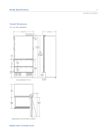
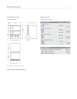
Site Preparation 10 Anti-Tip Bracket Installation To prevent the unit from tipping forward and provide a stable installation, the unit must be secured in place with the anti-tip bracket provided with the unit. An anti-tip bracket and hardware is provided with the integrated unit. Placement of the anti-tip bracket is critical to a stable installation. The anti-tip bracket must be installed on a solid base. If you are installing the unit in a space deeper than 24" (610), be sure to locate the anti-tip bracket so that it engages the unit properly. It is important that the anti-tip bracket is placed 24" (610) from the front of the unit (without panels) to the back of the anti-tip bracket. IMPORTANT NOTE: In some installations the subflooring or finished floor may require angling the wood screws used to fasten the anti-tip bracket to the back wall. WOOD FLOOR APPLICATIONS Use the six #12 x 21/2" wood screws and the six 1/4" flat washers provided. Drill pilot holes 3/16" (5) diameter maximum, and make sure the screws penetrate through the flooring material and into the wall plate a minimum of 3/4" (19). Make sure the screws hold tight. Refer to the illustration below. CONCRETE FLOOR APPLICATIONS Use the two 3/8" x 3 3/4" concrete wedge anchors, two #12 x 21/2" wood screws and two 1/4" flat washers provided. Make sure the anchors and screws hold tight. Refer to the illustration below. Anti-Tip Bracket Placement 27" (686) Models 36" (914) Models A 131/2" (343) 18" (457) Make sure there are no electrical wires or plumbing in the area which the screws could penetrate. A A FINISHED FLOORING WALL PLATE SUBFLOORING WOOD FLOOR Wood floor. A A FINISHED FLOORING WALL PLATE SUBFLOORING CONCRETE FLOOR 11/2"(38) min Concrete floor.
-
 1
1 -
2
-
3
-
4
-
 5
5 -
 6
6 -
 7
7 -
 8
8 -
 9
9 -
 10
10 -
 11
11 -
 12
12 -
 13
13 -
 14
14 -
 15
15 -
16
-
17
-
18
-
19
-
20
-
21
-
22
-
23
-
24
 |
 |
