Sub-Zero 736TFI Integrated Installation Guide
Sub-Zero 736TFI Manual
 |
View all Sub-Zero 736TFI manuals
Add to My Manuals
Save this manual to your list of manuals |
Sub-Zero 736TFI manual content summary:
- Sub-Zero 736TFI | Integrated Installation Guide - Page 1
INSTALLATION GUIDE Integrated Refrigeration - Sub-Zero 736TFI | Integrated Installation Guide - Page 2
Integrated Refrigeration 3 Model Specifications 4 Site Preparation 7 Integrated Installation 12 Service Information 22 Features and specifications are subject to change at any time without notice. Visit subzero.com/specs for the most up-todate information. IMPORTANT NOTE: Throughout this guide - Sub-Zero 736TFI | Integrated Installation Guide - Page 3
Integrated Refrigeration 3 subzero.com/specs Sub-Zero Integrated Refrigeration The importance of the installation of the Sub-Zero integrated unit cannot be overemphasized. Installation should be done by a qualified installer. Before you begin the installation process, it is recommended that you - Sub-Zero 736TFI | Integrated Installation Guide - Page 4
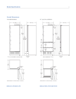
) 341/2" (876) HEIGHT DIMENSIONS ± 1/2" (13) 9 3/4" (248) 4" (102) 24" (610) 45/8" (117) 251/2" (648) 24" (610) 191/2" (495) 45/8" (117) 251/2" (648) DIMENSIONS WILL VARY WITH PANEL THICKNESS MODELS IC-27R AND IC-27FI DIMENSIONS WILL VARY WITH PANEL THICKNESS MODELS 700TR, 700TFI AND 700TCI - Sub-Zero 736TFI | Integrated Installation Guide - Page 5
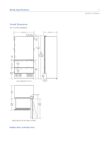
) TO TOP OF 3/8" OPENNG (10) 1/2" (13) 131/4" (337) 20 3/8" (518) 101/4" (260) 341/2" (876) HEIGHT DIMENSIONS ± 1/2" (13) 9 3/4" (248) 4" (102) 24" (610) 191/2" (495) 7" (178) 341/2" (876) DIMENSIONS WILL VARY WITH PANEL THICKNESS MODELS 736TR, 736TFI AND 736TCI 5 subzero.com/specs - Sub-Zero 736TFI | Integrated Installation Guide - Page 6
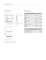
(13) 4" (102) 24" (610) 191/2" (495) 257/8" (657) DIMENSIONS WILL VARY WITH PANEL THICKNESS MODELS 700BR, 700BF(I) AND 700BC(I) Specifications INTEGRATED MODELS Interior Capacity COLUMN MODELS IC-27R IC-27FI 27" (686) TALL MODELS 700TR 700TFI 700TCI 36" (914) TALL MODELS 736TR 736TFI 736TCI 27 - Sub-Zero 736TFI | Integrated Installation Guide - Page 7
Dimensions INTEGRATED MODELS 25" (635) OPENING DEPTH TOP VIEW 7 subzero.com/specs IMPORTANT NOTE: The depth of each integrated DEPTH B OPENING HEIGHT A OPENING WIDTH SIDE VIEW Opening Dimensions IC-27R and IC-27FI 700TR, 700TFI, 700TCI 736TR, 736TFI, 736TCI 700BR, 700BF(I), 700BC(I) FRONT VIEW - Sub-Zero 736TFI | Integrated Installation Guide - Page 8
shaded area shown in the illustrations below. Follow the National Electrical Code and local codes and ordinances when installing the receptacle. A separate circuit, servicing only this appliance is required. A ground fault circuit interrupter (GFCI) is not recommended and may cause interruption of - Sub-Zero 736TFI | Integrated Installation Guide - Page 9
compressor tray. The tray must be slid forward for service. The water supply line should be connected to the house supply with an easily accessible shut-off valve between the supply and the unit. Do not use self-piercing valves. A saddle valve kit is available from your authorized Sub-Zero dealer - Sub-Zero 736TFI | Integrated Installation Guide - Page 10
integrated unit. Placement of the anti-tip bracket is critical to a stable installation. The anti-tip bracket must be installed on a solid base. If you are installing panels) to the back of the anti-tip bracket. IMPORTANT NOTE: In some installations screws hold tight. Refer to the illustration below - Sub-Zero 736TFI | Integrated Installation Guide - Page 11
subzero.com/specs Anti-Tip Bracket Installation INSTALL installation of the panels. Remove the decorative top and side moldings and the kickplate/grille. IMPORTANT NOTE: For drawer models, the top drawer has a control cable that needs to be disconnected before removing this drawer. Refer integrated - Sub-Zero 736TFI | Integrated Installation Guide - Page 12
and cooling. Press the UNIT ON/OFF key pad on the control panel (POWER for column models). Refer to the illustrations below. Once you are satisfied that the unit is operating properly, shut off power to the electrical outlet at the circuit breaker and proceed. If two integrated units are installed - Sub-Zero 736TFI | Integrated Installation Guide - Page 13
Integrated Installation 13 subzero.com/specs Molding Installation Install the decorative white molding strips to the top and sides of the integrated unit for a finished look. The top molding strip, used on column and tall models, must be installed before the side molding can be attached. The top - Sub-Zero 736TFI | Integrated Installation Guide - Page 14
panel dimensions before proceeding. Additional panel information can be found in the Sub-Zero design guide and on our website, subzero.com. IMPORTANT NOTE: A portion of the backside of the decorative panels will need to be finished, as they will be exposed when the doors are open. D-style handles - Sub-Zero 736TFI | Integrated Installation Guide - Page 15
Integrated Installation 15 subzero.com/specs Panel Considerations TYPICAL PANEL DIMENSIONS 26 3/4" (679) PANEL WIDTH 26 3/4" (679) PANEL WIDTH 1/8" (3) 1/8" (3) 1/8" (3) 35 3/4" (908) PANEL WIDTH 767/8" (1953) 45 3/8" (1153) 807/8" (2054) 45 3/8" (1153) 79 7/8" (2029) 4" (102) 27" (686) - Sub-Zero 736TFI | Integrated Installation Guide - Page 16
Integrated Installation 16 Panel Considerations DOOR PANEL HEIGHT The height of the door panel can extend beyond the typical panel height, provided you do not exceed the panel weight limit. A minimum finished height of 80" (2032) is required for 27" (686) and 36" (914) tall models. For the 27" ( - Sub-Zero 736TFI | Integrated Installation Guide - Page 17
Integrated Installation 17 subzero.com/specs Panel Installation DOOR PANEL INSTALLATION Remove the two pieces of mounting hardware attached to the front of the door and set aside. Place the door panel lying face down on a protected surface to ensure that the front is not scratched or damaged. - Sub-Zero 736TFI | Integrated Installation Guide - Page 18
Integrated Installation 18 Panel Installation PANEL BRACKET POSITIONING The illustrations below show placement of panel mounting brackets. Dimensions are based on a 4" (102) toe kick and a 1/8" (3) reveal. A reveal of up to 1/4" (6) is possible, but panel dimensions need to be adjusted accordingly - Sub-Zero 736TFI | Integrated Installation Guide - Page 19
Integrated Installation 19 subzero.com/specs Panel Installation DRAWER PANEL INSTALLATION Remove the mounting hardware provided and set aside. As with the door panel, you should work on the back side of each drawer panel the height and thickness of the panel. Refer to the illustration below. Secure - Sub-Zero 736TFI | Integrated Installation Guide - Page 20
side by side in a dual installation. Panel width dimensions will vary slightly from single installations. A dual installation kit is required for installations with 2" (51) or less space between units. Dual installation kits are available through your authorized Sub-Zero dealer. IMPORTANT NOTE: If - Sub-Zero 736TFI | Integrated Installation Guide - Page 21
in? Have stainless steel panels been inspected for any imperfections? This is to be done by the authorized Sub-Zero dealer or installer with the customer, upon completion of installation. Stainless steel panels are covered by a limited 60-day warranty for cosmetic defects. 21 subzero.com/specs - Sub-Zero 736TFI | Integrated Installation Guide - Page 22
, maintain the quality built into your integrated unit by calling Sub-Zero factory certified service. For the name and number of Sub-Zero factory certified service nearest you, check the contact & support section of our website, subzero.com or call Sub-Zero customer care at 800-222-7820. When - Sub-Zero 736TFI | Integrated Installation Guide - Page 23
part without the express written permission of Sub-Zero, Inc. ©Sub-Zero, Inc. all rights reserved. Wolf, Wolf & Design, Wolf Gourmet, W & Design and the color red as applied to knobs are registered trademarks and service marks of Wolf Appliance, Inc. Sub-Zero, Sub-Zero & Design, Dual Refrigeration - Sub-Zero 736TFI | Integrated Installation Guide - Page 24
SUB-ZERO, INC. P. O. BOX 44848 MADISON, WI 53744 SUBZERO.COM 800.222.7820 7023602 REV-A 8/2011
-
 1
1 -
 2
2 -
 3
3 -
 4
4 -
 5
5 -
 6
6 -
 7
7 -
8
-
9
-
10
-
11
-
12
-
13
-
14
-
15
-
16
-
17
-
18
-
19
-
20
-
21
-
22
-
23
-
24
 |
 |

INSTALLATION GUIDE
Integrated Refrigeration