Sub-Zero 736TFI Integrated Installation Guide - Page 9
Site Preparation, Plumbing Requirements
 |
View all Sub-Zero 736TFI manuals
Add to My Manuals
Save this manual to your list of manuals |
Page 9 highlights
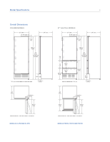
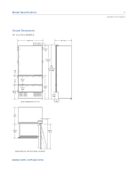
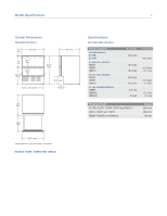
Site Preparation 9 subzero.com/specs Plumbing Requirements For integrated models with an automatic ice maker, the water supply line should be located through the floor or back wall, within the shaded area shown in the illustrations. Routing the line in these locations will avoid any interference with the anti-tip bracket. IMPORTANT NOTE: Do not route the water supply line in front of the compressor tray. The tray must be slid forward for service. The water supply line should be connected to the house supply with an easily accessible shut-off valve between the supply and the unit. Do not use self-piercing valves. A saddle valve kit is available from your authorized Sub-Zero dealer. An in-line filter is required when water conditions have a high sediment content. A reverse osmosis system can be used provided there is constant water pressure of 20 psi (1.4 bar) to 100 psi (6.9 bar) supplied to the unit at all times. In some cases, a reverse osmosis water filter system may not be able to maintain the minimum pressure consistently. A copper line is not recommended for this application. IMPORTANT NOTE: All installations must meet local plumbing code requirements. Plumbing Requirements Water Supply Line 1/4" OD copper, braided stainless steel or PEX tubing Water Pressure 20-100 psi (1.4-6.9 bar) Excess Water Line for Connection 27" (686) 3" (76) 21/2" (64) 131/2" (343) FLOOR 3/4" FRONT VIEW (19) BACK WALL 6" (152) 131/2" (343) 21/2" (64) 11/2" (38) 11/2" (38) TOP VIEW 36" (914) models. 3" (76) 21/2" (64) 9" (229) FLOOR 3/4" FRONT VIEW (19) BACK WALL 6" (152) 9" (229) 21/2" (64) 11/2" (38) 11/2" (38) TOP VIEW 27" (686) models.
-
 1
1 -
2
-
3
-
 4
4 -
 5
5 -
 6
6 -
 7
7 -
 8
8 -
 9
9 -
 10
10 -
 11
11 -
 12
12 -
 13
13 -
 14
14 -
15
-
16
-
17
-
18
-
19
-
20
-
21
-
22
-
23
-
24
 |
 |
