Sub-Zero IC-30FI Integrated Design Guide - Page 7
Electrical, Plumbing
 |
View all Sub-Zero IC-30FI manuals
Add to My Manuals
Save this manual to your list of manuals |
Page 7 highlights
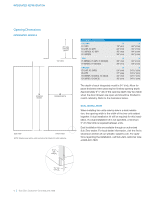
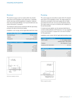
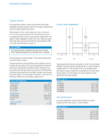
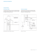
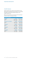
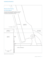
INTEGRATED REFRIGERATION Electrical The electrical supply must be located within the shaded area shown in the illustration and chart below. A separate circuit, servicing only this appliance is required. A ground fault circuit interrupter (GFCI) is not recommended and may cause interruption of operation. The electrical outlet must be positioned with the grounding prong to the right of the thinner blades. Installation must comply with all applicable electrical codes. ELECTRICAL REQUIREMENTS Electrical Supply Service Receptacle 115 VAC, 60 Hz 15 amp 3-prong grounding-type ELECTRICAL SUPPLY LOCATION MODEL 18" Model 24" Model 27" Model 30" Model 36" Model A 6" (152) 91/2" (241) 11" (279) 121/2" (318) 151/2" (394) LEFT SIDE OF OPENING Plumbing The water supply line should be located within the shaded area shown in the illustration below. The water supply line should be connected to the house supply with an easily accessible shut-off valve. Do not use self‑piercing valves. The water supply line must not interfere with installation of the anti-tip bracket. A reverse osmosis system can be used provided there is constant water pressure of 35-120 psi (2.4-8.3 bar) supplied to the unit at all times. A copper line is not recommended for this application. Installation must comply with all applicable plumbing codes. PLUMBING REQUIREMENTS Water Supply Pressure Excess Line for Connection 1/4" OD copper, braided stainless steel or PEX tubing 35-120 psi (2.4-8.3 bar) 36" (914) WATER SUPPLY LOCATION MODEL 18" Model 24" Model 30" Model 36" Model A 3" (76) 51/2" (140) 6" (152) 9" (229) 41/2" A (114) 1/4" (6) FLOOR 41/4" (108) Electrical supply location. RIGHT SIDE OF OPENING A 6" (152) 3" (76) AREA EXTENDS 1/2" (13) FORWARD ON FLOOR Water supply location. subzero.com/specs | 7
-
 1
1 -
 2
2 -
 3
3 -
 4
4 -
 5
5 -
 6
6 -
 7
7 -
 8
8 -
 9
9 -
 10
10 -
 11
11 -
 12
12 -
13
-
14
 |
 |
