2
TASCAM IF-SM/DM Owner’s Manual
Contents
1 – Introduction
Installation
............................................
3
Connections
...........................................
4
Monitor alignment
...............................
4
2 – Using the card
OPERATION option
...............................
5
Muting channels
............................
5
Soloing channels
............................
6
Downmix on/off
............................
6
Bass management
.........................
6
Alternative speakers
.....................
6
Oscillator routing
...........................
6
To 2.1
.............................................
6
SPL reference and level
.................
6
Notes on other hardware controls ...6
ROUTING option
...................................
7
Monitoring keys
............................
7
Output routing
..............................
7
DOWNMIX option
.................................
8
6.1 format
.......................................
9
5.1 format
.....................................
10
LRCS format
.................................
11
Stereo format
...............................
12
BASS MANAGEMENT option
..............
13
Type 1 bass management
...........
13
Type 2 bass management
...........
13
MONITOR ALIGNMENT option
...........
14
Trimming the levels
.....................
14
Generating the pink noise
..........
15
Setting the surround speaker level ...15
Adjusting the LFE GAIN
...............
15
Channel delay
..............................
15
Setting the overall surround level ... 16
3 – Reference
Block diagram
......................................
17
Level diagram
......................................
18
Audio performance
.............................
18
Table of figures
Figure 1.1: Fitting the card
. . . . . . . . . . . . . . . . . . . . . . . . . . . . . . . . . . . . . . . . . . . . . . . . . . . . . 3
Table 1.2: Pin assignments of the IF-SM/DM analog outputs . . . . . . . . . . . . . . . . . . . . . . . . . . 4
Figure 2.1: The main surround monitor screen
. . . . . . . . . . . . . . . . . . . . . . . . . . . . . . . . . . . . . 5
Figure 2.2: The OPERATION option . . . . . . . . . . . . . . . . . . . . . . . . . . . . . . . . . . . . . . . . . . . . . . . 5
Figure 2.3: SHIFTed number keys used for channel control
. . . . . . . . . . . . . . . . . . . . . . . . . . . 5
Figure 2.4: ROUTING option screen
. . . . . . . . . . . . . . . . . . . . . . . . . . . . . . . . . . . . . . . . . . . . . . 7
Figure 2.5: Example downmix screen showing attenuation points . . . . . . . . . . . . . . . . . . . . . 8
Table 2.6: 6.1 to 5.1 downmix pattern . . . . . . . . . . . . . . . . . . . . . . . . . . . . . . . . . . . . . . . . . . . . 9
Table 2.7: 6.1 to 2.1 downmix pattern . . . . . . . . . . . . . . . . . . . . . . . . . . . . . . . . . . . . . . . . . . . . 9
Table 2.8: 6.1 to stereo downmix pattern
. . . . . . . . . . . . . . . . . . . . . . . . . . . . . . . . . . . . . . . . . 9
Table 2.9: 6.1 to mono downmix pattern . . . . . . . . . . . . . . . . . . . . . . . . . . . . . . . . . . . . . . . . . . 9
Table 2.10: 5.1 to phantom rear LRCS downmix pattern
. . . . . . . . . . . . . . . . . . . . . . . . . . . . 10
Table 2.11: 5.1 to hard rear LRCS downmix pattern
. . . . . . . . . . . . . . . . . . . . . . . . . . . . . . . . 10
Table 2.12: 5.1 to 2.1
. . . . . . . . . . . . . . . . . . . . . . . . . . . . . . . . . . . . . . . . . . . . . . . . . . . . . . . . . 10
Table 2.13: 5.1 to stereo downmix pattern
. . . . . . . . . . . . . . . . . . . . . . . . . . . . . . . . . . . . . . . 10
Table 2.14: 5.1 to mono downmix pattern . . . . . . . . . . . . . . . . . . . . . . . . . . . . . . . . . . . . . . . . 11
Table 2.15: LRCS to stereo downmix pattern . . . . . . . . . . . . . . . . . . . . . . . . . . . . . . . . . . . . . . 11
Table 2.16: LRCS to mono downmix pattern . . . . . . . . . . . . . . . . . . . . . . . . . . . . . . . . . . . . . . 12
Table 2.17: LRCS to LRCS with phantom rear downmix pattern
. . . . . . . . . . . . . . . . . . . . . . 12
Figure 2.18: Stereo to mono downmix . . . . . . . . . . . . . . . . . . . . . . . . . . . . . . . . . . . . . . . . . . . 12
Figure 2.19: Example downmix screen showing attenuation points . . . . . . . . . . . . . . . . . . . 13
Figure 2.20: Type 1 and Type 2 bass management for 5.1 and 6.1 settings
. . . . . . . . . . . . . 13
Figure 2.21: Example downmix screen showing attenuation points . . . . . . . . . . . . . . . . . . . 14
Figure 3.1: Block diagram
. . . . . . . . . . . . . . . . . . . . . . . . . . . . . . . . . . . . . . . . . . . . . . . . . . . . . 17
Figure 3.2: Level diagram
. . . . . . . . . . . . . . . . . . . . . . . . . . . . . . . . . . . . . . . . . . . . . . . . . . . . . 18
 1
1 2
2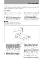 3
3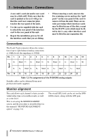 4
4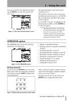 5
5 6
6 7
7 8
8

