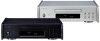
TEAC PD-505T Owners Manual English Francais Espanol - Page 10
Connections, Power inlet ~IN
 |
View all TEAC PD-505T manuals
Add to My Manuals
Save this manual to your list of manuals |
Page 10 highlights
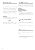
Connections VVAfter all connections are complete, connect the power cord's plug to the AC wall outlet. oo Read the instructions of each device that you intend to use with this unit. oo Do not bundle connecting cables with power cords. Doing so could cause noise. oo Connect all plugs completely. Included power cord RCA coaxial digital cable Optical digital cable BNC coaxial cable CLOCK OUT Optical digital input DIGITAL IN (OPTICAL) Coaxial digital input DIGITAL IN (COAXIAL) c Wall outlet Device that outputs clock signal Digital audio input device Digital audio input device A UPDATE (maintenance) port This is used for maintenance. Do not connect anything to this port unless instructed to do so by our service department. B CLOCK sync input (10MHz IN) connector Use this connector to input 10MHz clock synchronization signals (page 23). Use a commercially available BNC coaxial cable for connection. C COAXIAL/OPTICAL digital audio output connectors Use these to output digital audio. Connect digital audio input connectors of audio devices here. Use commercially-available RCA coaxial digital cables or rectangular optical digital cables for connection. D Power inlet (~IN) Connect the supplied power cord here. After all other connections are complete, connect the power cord's plug to a wall outlet. VVDo not use any power cord other than the one included with this unit. Use of other power cords could result in fire or electric shock. VVDisconnect the power plug from the outlet if you will not use the unit for a long time. 10
-
 1
1 -
2
-
3
-
4
-
 5
5 -
 6
6 -
 7
7 -
 8
8 -
 9
9 -
 10
10 -
 11
11 -
 12
12 -
 13
13 -
 14
14 -
 15
15 -
16
-
17
-
18
-
19
-
20
-
21
-
22
-
23
-
24
-
25
-
26
-
27
-
28
-
29
-
30
-
31
-
32
-
33
-
34
-
35
-
36
-
37
-
38
-
39
-
40
-
41
-
42
-
43
-
44
-
45
-
46
-
47
-
48
-
49
-
50
-
51
-
52
-
53
-
54
-
55
-
56
-
57
-
58
-
59
-
60
-
61
-
62
-
63
-
64
-
65
-
66
-
67
-
68
-
69
-
70
-
71
-
72
 |
 |
