TP-Link EAP330 EAP330 V1 Quick Install Guide - Page 1
TP-Link EAP330 Manual
 |
View all TP-Link EAP330 manuals
Add to My Manuals
Save this manual to your list of manuals |
Page 1 highlights
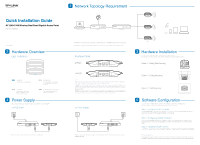
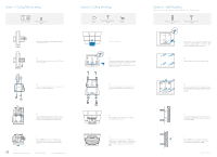
Quick Installation Guide AC1200/1900 Wireless Dual Band Gigabit Access Point EAP320 / EAP330 7106505995 REV1.0.0 2 Hardware Overview LED Indication Solid green The device is working properly. Flashing yellow Firmware update is in progress. Do not disconnect or power off the device. Flashing red System errors. RAM, Flash, Ethernet, WLAN or firmware may be malfunctioning. Double-flashing red, green, yellow The device is being reset to its factory default settings. 4 Power Supply EAP can be powered via a PSE device (such as a PoE switch) or a power adapter. Via PoE Switch PoE Switch Connect the Ethernet cable from the PoE switch to the ETHERNET port. 1 Network Topology Requirement Internet EAP Controller Controller Host Router PoE Switch A DHCP server (typically a router) is required to assign IP addresses to the EAP and clients in your local network. A computer running the EAP Controller software can locate in the same or different subnet with the EAPs. Interface Panel EAP320 POWER ETHERNET CONSOLE RESET EAP330 POWER ETH1(PoE) ETH2 RESET NOTE: With the device powered on, press and hold the RESET button for about 8 seconds until the LED flashes red, then release the button. The device will restore to factory default settings. ETHERNET of EAP320 and ETH1 (PoE) of EAP330 is to connect to a router or a switch to transmit data or to a PSE (Power Sourcing Equipment), such as a PoE switch, for both data transmission and Power over Ethernet (PoE) through Ethernet cabling. ETH1 and ETH2 can be combined together to double the network backhaul capacity. CONSOLE is used to connect to the serial port of a computer or a terminal to check and monitor system information of the EAP device. CLI commands are not available in current software version. We will release a new version supporting CLI commands soon. Please pay close attention to our official website. Via Power Adapter Switch Plug one end of the provided power adapter into the POWER port of the EAP and the other end to a standard electrical wall outlet. EAP EAP Clients EAP 3 Hardware Installation The EAP can be ceiling rail mounted, ceiling-mounted, and wall-mounted. The instructions for various mounting options are on the back of this Quick Installation Guide. Option 1: Ceiling Rail Mounting Option 2: Ceiling Mounting Option 3: Wall Mounting 5 Software Configuration To quickly set up a wireless network connection with mass EAPs, please follow the steps below. Note: The IP address of the management computer must be reachable for the EAPs in the network. Step 1: Installing the EAP Controller Find the EAP Controller application file (for Windows user only) from our website at www.tp-link.com. Run the file and follow the wizard to install the EAP Controller on the computer. Step 2: Configuring the EAP Controller Launch the EAP Controller and follow the configuration wizard to create a primary wireless network. After the wizard is finished, a login screen will appear. Enter the admin name and password you created and click Sign In. Step 3: Adopting the EAP devices Adopt the EAP devices in the Controller management interface to change the status from pending to connected. For More Configurations Now you can manage your wireless network and view network statistic using the EAP Controller. Please refer to the EAP Controller User Guide to learn more information on configuring and using the Controller software.
-
 1
1 -
 2
2
 |
 |