TP-Link T1600G-52TSTL-SG2452 T1600G-28TS V1 User Guide
TP-Link T1600G-52TSTL-SG2452 Manual
 |
View all TP-Link T1600G-52TSTL-SG2452 manuals
Add to My Manuals
Save this manual to your list of manuals |
TP-Link T1600G-52TSTL-SG2452 manual content summary:
- TP-Link T1600G-52TSTL-SG2452 | T1600G-28TS V1 User Guide - Page 1
T1600G-28TS (TL-SG2424) T1600G-52TS (TL-SG2452) T1600G-28PS (TL-SG2424P) T1600G-52PS (TL-SG2452P) JetStream Gigabit Smart Switch REV1.1.2 1910011399 - TP-Link T1600G-52TSTL-SG2452 | T1600G-28TS V1 User Guide - Page 2
. This equipment generates, uses, and can radiate radio frequency energy and, if not installed and used in accordance with the instruction manual, may cause harmful interference to radio communications. Operation of this equipment in a residential area is likely to cause harmful interference - TP-Link T1600G-52TSTL-SG2452 | T1600G-28TS V1 User Guide - Page 3
source. Don't disassemble the product, or make repairs yourself. You run the risk of electric shock and voiding the limited warranty. If you need service, please contact us. Avoid water and wet locations. This product can be used in the following countries: AT BG BY CA CZ DE DK - TP-Link T1600G-52TSTL-SG2452 | T1600G-28TS V1 User Guide - Page 4
CONTENTS Package Contents ...1 Chapter 1 About this Guide...2 1.1 Intended Readers...2 1.2 Conventions...2 1.3 Overview of This Guide 2 Chapter 2 Introduction...6 2.1 Overview of the Switch 6 2.2 Appearance Description 6 2.2.1 Front Panel...6 2.2.2 Rear Panel ...11 Chapter 3 Login to the Switch - TP-Link T1600G-52TSTL-SG2452 | T1600G-28TS V1 User Guide - Page 5
Chapter 5 Switching ...46 5.1 Port...46 5.1.1 Port Config ...46 5.1.2 Port Mirror ...47 5.1.3 Port Security 49 5.1.4 Port Isolation 51 5.1.5 Loopback Detection 52 5.2 LAG ...54 5.2.1 LAG Table...55 5.2.2 Static LAG ...56 5.2.3 LACP Config 57 5.3 Traffic Monitor ...59 5.3.1 Traffic Summary 59 - TP-Link T1600G-52TSTL-SG2452 | T1600G-28TS V1 User Guide - Page 6
7.2 Port Config...93 7.3 MSTP Instance...94 7.3.1 Region Config 95 7.3.2 Instance Config 95 7.3.3 Instance Port Config 96 7.4 STP Security...98 7.4.1 Port Protect 98 7.4.2 TC Protect 101 7.5 Application Example for STP Function 101 Chapter 8 Multicast ...106 8.1 IGMP Snooping...110 8.1.1 - TP-Link T1600G-52TSTL-SG2452 | T1600G-28TS V1 User Guide - Page 7
9.4 ARP ...148 9.4.1 ARP Table 148 9.4.2 Static ARP 148 Chapter 10QoS...149 10.1 DiffServ...152 10.1.1 Port Priority 152 10.1.2 Schedule Mode 153 10.1.3 802.1P Priority 154 10.1.4 DSCP Priority 155 10.2 Bandwidth Control 157 10.2.1 Storm Control 157 10.3 Voice VLAN...158 10.3.1 Rate Limit - TP-Link T1600G-52TSTL-SG2452 | T1600G-28TS V1 User Guide - Page 8
VLAN Binding 184 12.5 Application Example for ACL 184 Chapter 13Network Security 187 13.1 IP-MAC Binding ...187 13.1.1 Binding Table 187 13.1.2 Manual Binding 188 13.1.3 ARP Scanning 190 13.2 DHCP Snooping...191 13.2.1 Global Config 195 13.2.2 Port Config 196 13.3 ARP Inspection ...197 13 - TP-Link T1600G-52TSTL-SG2452 | T1600G-28TS V1 User Guide - Page 9
14.3.4 Alarm Config 231 Chapter 15 LLDP ...233 15.1 Basic Config...237 15.1.1 Global Config 237 15.1.2 Port Config 238 15.2 Device Info ...239 15.2.1 Local Info...239 15.2.2 Neighbor Info 240 15.3 Device Statistics...241 15.4 LLDP-MED...242 15.4.1 Global Config 243 15.4.2 Port Config 244 15 - TP-Link T1600G-52TSTL-SG2452 | T1600G-28TS V1 User Guide - Page 10
Resource CD for T1600-28TS/T1600G-52TS/T1600G-28PS/T1600G-52PS, including: • This User Guide • CLI Reference Guide • SNMP Mibs • 802.1X Client Software and its User Guide • Other Helpful Information Note : Make sure that the package contains the above items. If any of the listed items are damaged - TP-Link T1600G-52TSTL-SG2452 | T1600G-28TS V1 User Guide - Page 11
Info menu option that is located under the System menu. Bold font indicates a button, a toolbar icon, menu or menu item. Symbols in this Guide: Symbol De scription Note : Tips: Ignoring this type of note might result in a malfunction or damage to the device. This format indicates important - TP-Link T1600G-52TSTL-SG2452 | T1600G-28TS V1 User Guide - Page 12
Chapte r Chapter 4 System Chapter 5 Switching Chapter 6 VLAN Chapter 7 Spanning Tree Chapter 8 Multicast Chapter 9 Routing Introduction This module is used to configure system properties of the switch. Here mainly introduces: • System Info: Configure the description, system time and network - TP-Link T1600G-52TSTL-SG2452 | T1600G-28TS V1 User Guide - Page 13
used to configure QoS function to provide different quality of service for various network applications and requirements. Here mainly introduces: control mechanism for LAN ports to solve mainly authentication and security problems. Chapter 14 SNMP This module is used to configure SNMP function - TP-Link T1600G-52TSTL-SG2452 | T1600G-28TS V1 User Guide - Page 14
module is used to configure LLDP function to provide information for SNMP applications to simplify troubleshooting. Here mainly introduces: • Basic Config: Configure the LLDP parameters of the device. specifications of the switch. Lists the glossary used in this manual. Return to CONTENTS 5 - TP-Link T1600G-52TSTL-SG2452 | T1600G-28TS V1 User Guide - Page 15
L2 and L2+ management features. It provides a variety of service features and multiple powerful functions with high security. The EIA- Sourcing Equipment (PSE*). All the Ethernet RJ45 ports on the switch support Power over Ethernet (PoE*) function, which can automatically detect and supply - TP-Link T1600G-52TSTL-SG2452 | T1600G-28TS V1 User Guide - Page 16
Each has a corresponding 10/100/1000Mbps LED. SFP Ports: Designed to install the SFP module. T1600G-52TS features 4 individual SFP ports and supports 1000M SFP module connection only. LEDs Name Status Indication PWR On Flashing The switch is powered on Power supply is abnormal Off The - TP-Link T1600G-52TSTL-SG2452 | T1600G-28TS V1 User Guide - Page 17
1000Mbps. Each has a corresponding Speed or PoE LED. SFP Ports: Designed to install the SFP module. T1600G-28PS features 4 individual SFP ports and supports 1000M SFP module connection only. LEDs T1600G-28PS has an LED mode switch button which is for switching the LED status indication. When the - TP-Link T1600G-52TSTL-SG2452 | T1600G-28TS V1 User Guide - Page 18
When the Speed LED is on, the port LED is indicating the data transmission status. Name Status Indication On The switch is powered on PWR Flashing Power supply is abnormal Off The switch is powered off or power supply is abnormal Flashing The switch works properly SYS On/Off The - TP-Link T1600G-52TSTL-SG2452 | T1600G-28TS V1 User Guide - Page 19
1000Mbps. Each has a corresponding Speed or PoE LED. SFP Ports: Designed to install the SFP module. T1600G-52PS features 4 individual SFP ports and supports 1000M SFP module connection only. LEDs T1600G-52PS has an LED mode switch button which is for switching the LED status indication. When the - TP-Link T1600G-52TSTL-SG2452 | T1600G-28TS V1 User Guide - Page 20
Name Status Indication 1000Base-X (port 49-52) On Flashing Off A 1000Mbps device is connected to the corresponding port Data is being transmitted or received A 10/100Mbps device or no device is connected to the corresponding port When the PoE LED is on, the port LED is indicating the power - TP-Link T1600G-52TSTL-SG2452 | T1600G-28TS V1 User Guide - Page 21
Grounding Terminal: The switch already comes with Lightning Protection Mechanism. You can also ground the switch through the PE (Protecting Earth) cable of AC cord or with Ground Cable. Return to CONTENTS 12 - TP-Link T1600G-52TSTL-SG2452 | T1600G-28TS V1 User Guide - Page 22
Chapter 3 Login to the Switch 3.1 Login 1) To access the configuration utility, open a web-browser and type in the default address http://192.168.0.1 in the address field of the browser, then press the Enter key. Figure 3-1 Web-browser Tips: To log in to the switch, the IP address of your PC should - TP-Link T1600G-52TSTL-SG2452 | T1600G-28TS V1 User Guide - Page 23
3.2 Configuration After a successful login, the main page will appear as Figure 3-3, and you can configure the function by clicking the setup menu on the left side of the screen. Figure 3-3 Main Setup-Menu Note : Clicking Apply can only make the new configurations effective before the switch is - TP-Link T1600G-52TSTL-SG2452 | T1600G-28TS V1 User Guide - Page 24
Chapter 4 System The System module is mainly for system configuration of the switch, including four submenus: System Info, User M anagement, System Tools and Access Security. 4.1 System Info The System Info, mainly for basic properties configuration, can be implemented on System Summary, Device - TP-Link T1600G-52TSTL-SG2452 | T1600G-28TS V1 User Guide - Page 25
Port Info Port: Type : Rate : Status: Displays the port number of the switch. Displays the type of the port. Displays the maximum transmission rate of the port. Displays the connection status of the port. Click a port to display the bandwidth utilization on this port. The actual rate divided by - TP-Link T1600G-52TSTL-SG2452 | T1600G-28TS V1 User Guide - Page 26
is running. On this page you can configure the system time and the settings here will be used for other time-based functions. You can manually set the system time, get time from an NTP server or synchronize with PC's clock as the system time. Choose the menu System→System Info - TP-Link T1600G-52TSTL-SG2452 | T1600G-28TS V1 User Guide - Page 27
Config M anual: Get Time from NTP Se rv er: Synchronize with PC'S Clock: When this option is selected, you can set the date and time manually. When this option is selected, you can configure the time zone and the IP Address for the NTP Server. The switch will get UTC automatically - TP-Link T1600G-52TSTL-SG2452 | T1600G-28TS V1 User Guide - Page 28
Protocol version 4). Compared with IPv4, IPv6 increases the IP address size from 32 bits to 128 bits; this solves the IPv4 address exhaustion problem. IPv6 features IPv6 has the following features: 1. Adequate address space: The source and destination IPv6 addresses are both 128 bits (16 bytes - TP-Link T1600G-52TSTL-SG2452 | T1600G-28TS V1 User Guide - Page 29
solutions and improves the interoperability between different IPv6 applications. 5. Automatic address configuration: To simplify the host configuration, IPv6 supports stateful and stateless address configuration. Stateful address configuration means that a host acquires an IPv6 address and related - TP-Link T1600G-52TSTL-SG2452 | T1600G-28TS V1 User Guide - Page 30
Note : Two colons (::) can be used only once in an IPv6 address, usually to represent the longest successive hexadecimal fields of zeros. If two colons are used more than once, the device is unable to determine how many zeros double-colons represent when converting them to zeros to restore a 128-bit - TP-Link T1600G-52TSTL-SG2452 | T1600G-28TS V1 User Guide - Page 31
subnet prefix and an interface ID. Subnet Prefix: This section is allocated by the IANA (The Internet Assigned Numbers Authority), the ISP (Internet Service Provider) or the organizations. Interface ID: An interface ID is used to identify interfaces on a link. The interface ID must be unique to - TP-Link T1600G-52TSTL-SG2452 | T1600G-28TS V1 User Guide - Page 32
The figure below shows the structure of a global unicast address. Figure 4-7 Global Unicast Address Format Link-local address A link-local address is an IPv6 unicast address that can be automatically configured on any interface using the link-local prefix FE80::/10 (1111 1110 10) and the interface - TP-Link T1600G-52TSTL-SG2452 | T1600G-28TS V1 User Guide - Page 33
packet header, on the local link. After the source node receives the neighbor advertisement, the source node and destination node can communicate. Neighbor advertisement messages are also sent when there is a change in the link-layer address of a node on a local link. Address Resolution The address - TP-Link T1600G-52TSTL-SG2452 | T1600G-28TS V1 User Guide - Page 34
2. IPv6 Router Advertisement Message Router advertisement (RA) messages, which have a value of 134 in the Type field of the ICMP packet header, are periodically sent out each configured interface of an IPv6 router. RA messages typically include the following information: One or more onlink IPv6 - TP-Link T1600G-52TSTL-SG2452 | T1600G-28TS V1 User Guide - Page 35
port channel. Link-local Address Config Config Mode: Select the link-local address configuration mode. Manual: When this option is selected, you should assign a link-local address manually. Auto: When this option is selected, the switch will generate a link-local address automatically. 26 - TP-Link T1600G-52TSTL-SG2452 | T1600G-28TS V1 User Guide - Page 36
DHCPv6 Server: When this option is enabled, the system will try to obtain the global address from the DHCPv6 Server. Add a global address manually Address Format: Global Address: You can select the global address format according to your requirements. EUI-64: Indicates that you only need to - TP-Link T1600G-52TSTL-SG2452 | T1600G-28TS V1 User Guide - Page 37
access the switch using this address. Tips: After adding a global IPv6 address to your switch manually here, you can configure your PC's global IPv6 address in the same subnet with the switch Web management pages contained in this guide are subject to the admin's login without any explanation. 28 - TP-Link T1600G-52TSTL-SG2452 | T1600G-28TS V1 User Guide - Page 38
Choose the menu System→User M anagement→User Config to load the following page. Figure 4-11 User Config The following entries are displayed on this screen: User Info User Name: Create a name for users' login. Access Level: Password: Confirm Password: Select the access level to login. Guest: - TP-Link T1600G-52TSTL-SG2452 | T1600G-28TS V1 User Guide - Page 39
4.3.1 Boot Config On this page you can configure the boot file of the switch. When the switch is powered on, it will start up with the startup image. If it fails, it will try to start up with the backup image. If this fails too, you will enter into the bootutil menu of the switch. Choose the menu - TP-Link T1600G-52TSTL-SG2452 | T1600G-28TS V1 User Guide - Page 40
Backup Image: Select the backup boot image. 4.3.2 Config Restore On this page you can upload a backup configuration file to restore your switch to this previous configuration. Choose the menu System→System Tools→Config Restore to load the following page. Figure 4-13 Config Restore The following - TP-Link T1600G-52TSTL-SG2452 | T1600G-28TS V1 User Guide - Page 41
Choose the menu System→System Tools→Config Backup to load the following page. Figure 4-14 Config Backup The following entries are displayed on this screen: Config Backup Target Unit: Select a member switch to export the configuration file. Click the Export button to save the current startup - TP-Link T1600G-52TSTL-SG2452 | T1600G-28TS V1 User Guide - Page 42
is not checked, the uploaded firmware file will take place of the Backup Image. To start with the uploaded firmware, you should exchange the Next Startup Image and Backup Image in Boot Config and reboot the switch. Note : 1. Upgrading the firmware will only upgrade the backup image. 2. You are - TP-Link T1600G-52TSTL-SG2452 | T1600G-28TS V1 User Guide - Page 43
4.4 Access Security Access Security provides different security measures for the remote login so as to enhance the configuration management security. It can be implemented on Access Control, HTTP Config, HTTPS Config, SSH Config and Te lne t Config pages. 4.4.1 Access Control On this page you can - TP-Link T1600G-52TSTL-SG2452 | T1600G-28TS V1 User Guide - Page 44
IP Address & M ask MAC Address: Port: These fields is available to configure only when IP-based mode is selected. Only the users within the IP-range you set here are allowed for login. The field is available to configure only when MAC-based mode is selected. Only the user with this MAC Address you - TP-Link T1600G-52TSTL-SG2452 | T1600G-28TS V1 User Guide - Page 45
through ecommerce and online banking. SSL mainly provides the following services: 1. Authenticate the users and the servers based on the to trusted certificates or continue to this website. The switch also supports HTTPS connection for IPv6. After configuring an IPv6 address (for example - TP-Link T1600G-52TSTL-SG2452 | T1600G-28TS V1 User Guide - Page 46
Choose the menu System→Access Security→HTTPS Config to load the following page. Figure 4-20 HTTPS Config The following entries are displayed on this screen: Global Config HTTPS: SSL Version 3: Select Enable/Disable the HTTPS function on the switch. Enable or Disable Secure Sockets Layer - TP-Link T1600G-52TSTL-SG2452 | T1600G-28TS V1 User Guide - Page 47
CipherSuite Config RSA_WITH_RC4_128_M D5: Key exchange with RC4 128-bit encryption and MD5 for message digest. By default, it's enabled. RSA_WITH_RC4_128_SHA: Key exchange with RC4 128-bit encryption and SHA for message digest. By default, it's enabled. RSA_WITH_DES_CBC_SHA: Key exchange - TP-Link T1600G-52TSTL-SG2452 | T1600G-28TS V1 User Guide - Page 48
the client sends authentication request to the server for login, and then the two can communicate with each other after successful authentication. This switch supports SSH server and you can log on to the switch via SSH connection using SSH client software. SSH key can be downloaded into the switch - TP-Link T1600G-52TSTL-SG2452 | T1600G-28TS V1 User Guide - Page 49
Check the box to enable the corresponding data integrity algorithm. Key Download Key Type: Select the type of SSH Key to download. The switch supports two types: SSH-2 RSA/DSA and SSH-1 RSA. Key File: Download: Please ensure the key length of the downloaded file is in the range - TP-Link T1600G-52TSTL-SG2452 | T1600G-28TS V1 User Guide - Page 50
2. Click the Open button in the above figure to log on to the switch. Enter the login user name and password, and then you can continue to configure the switch. Application Example 2 for SSH: Network Requirements 1. Log on to the switch via key authentication using SSH and the SSH function is - TP-Link T1600G-52TSTL-SG2452 | T1600G-28TS V1 User Guide - Page 51
Configuration Procedure 1. Select the key type and key length, and generate SSH key. Note: 1. The key length is in the range of 512 to 3072 bits. 2. During the key generation, randomly moving the mouse quickly can accelerate the key generation. 42 - TP-Link T1600G-52TSTL-SG2452 | T1600G-28TS V1 User Guide - Page 52
2. After the key is successfully generated, please save the public key and private key to the computer. 3. On the Web management page of the switch, download the public key file saved in the computer to the switch. Note: 1. The key type should accord with the type of the key file. 2. The SSH key - TP-Link T1600G-52TSTL-SG2452 | T1600G-28TS V1 User Guide - Page 53
4. After the public key and private key are downloaded, please log on to the interface of PuTTY and enter the IP address for login. 5. Click Browse to download the private key file to SSH client software and click Open. 44 - TP-Link T1600G-52TSTL-SG2452 | T1600G-28TS V1 User Guide - Page 54
After successful authentication, please enter the login user name. If you log on to the switch without entering password, it indicates that the key has been successfully downloaded. 4.4.5 Telnet Config On this page you can Enable/Disable Telnet function globally on the switch. Choose the menu - TP-Link T1600G-52TSTL-SG2452 | T1600G-28TS V1 User Guide - Page 55
Chapter 5 Switching Switching module is used to configure the basic functions of the switch, including four submenus: Port, LAG, Traffic Monitor and MAC Address. 5.1 Port The Port function, allowing you to configure the basic features for the port, is implemented on the Port Config, Port Mirror, - TP-Link T1600G-52TSTL-SG2452 | T1600G-28TS V1 User Guide - Page 56
port). Usually, the mirroring port is connected to a data diagnose device, which is used to analyze the mirrored packets for monitoring and troubleshooting the network. Choose the menu Switching→Port→Port Mirror to load the following page. Figure 5-2 Mirror Group List The following entries are - TP-Link T1600G-52TSTL-SG2452 | T1600G-28TS V1 User Guide - Page 57
Source : Ope ration: Displays the mirrored ports. You can configure the mirror session by clicking Edit, or clear the mirror session configuration by clicking the Clear. Click Edit to display the following figure. Figure 5-3 Port Mirror Config The following entries are displayed on this screen: - TP-Link T1600G-52TSTL-SG2452 | T1600G-28TS V1 User Guide - Page 58
Egre ss: LAG: Select Enable/Disable the Egress feature. When the Egress is enabled, the outgoing packets sent by the mirrored port will be copied to the mirroring port. Displays the LAG number which the port belongs to. The LAG member cannot be selected as the mirrored port or mirroring port. Note - TP-Link T1600G-52TSTL-SG2452 | T1600G-28TS V1 User Guide - Page 59
. Static: When Static mode is selected, the learned MAC address will be out of the influence of the aging time and can only be deleted manually. The learned entries will be cleared after the switch is rebooted. Permanent: When Permanent mode is selected, the learned MAC address will be out of - TP-Link T1600G-52TSTL-SG2452 | T1600G-28TS V1 User Guide - Page 60
Status: Select Enable/Disable the Port Security feature for the port. Note : The Port Security function is disabled for the LAG port member. Only the port is removed from the LAG, will the Port Security function be available for the port. 5.1.4 Port Isolation Port Isolation provides a method of - TP-Link T1600G-52TSTL-SG2452 | T1600G-28TS V1 User Guide - Page 61
Click Edit to display the following figure. Figure 5-6 Port Isolation Config 5.1.5 Loopback Detection With loopback detection feature enabled, the switch can detect loops using loopback detection packets. When a loop is detected, the switch will display an alert or further block the corresponding - TP-Link T1600G-52TSTL-SG2452 | T1600G-28TS V1 User Guide - Page 62
Choose the menu Switching→Port→Loopback De tection to load the following page. Figure 5-7 Loopback Detection Config The following entries are displayed on this screen: Global Config LoopbackDe tection Status: Detection Interval: Automatic Re cov ery Time : Web Refresh Status: Web Refresh - TP-Link T1600G-52TSTL-SG2452 | T1600G-28TS V1 User Guide - Page 63
is detected. Displays the port status about block or unblock. Displays the LAG number the port belongs to. Click the Recover button to manually remove the block status of selected ports. Note : Loopback Detection must coordinate with storm control. 5.2 LAG LAG (Link Aggregation Group) is to combine - TP-Link T1600G-52TSTL-SG2452 | T1600G-28TS V1 User Guide - Page 64
The LAG function is implemented on the LAG Table, Static LAG and LACP Config configuration pages. 5.2.1 LAG Table On this page, you can view the information of the current LAG of the switch. Choose the menu Switching→LAG→LAG Table to load the following page. Figure 5-8 LAG Table The following - TP-Link T1600G-52TSTL-SG2452 | T1600G-28TS V1 User Guide - Page 65
of the LAG. Click the Detail button for the detailed information of your selected LAG. Figure 5-9 Detailed Information 5.2.2 Static LAG On this page, you can manually configure the LAG. Choose the menu Switching→LAG→Static LAG to load the following page. Figure 5-10 - TP-Link T1600G-52TSTL-SG2452 | T1600G-28TS V1 User Guide - Page 66
De scription: Member Port Member Port: Displays the description of the LAG. Select the port as the LAG member. Clearing all the ports of the LAG will delete this LAG. Tips: 1. The LAG can be deleted by clearing its all member ports. 2. A port can only be added to a LAG. If a port is the member - TP-Link T1600G-52TSTL-SG2452 | T1600G-28TS V1 User Guide - Page 67
On this page, you can configure the LACP feature of the switch. Choose the menu Switching→LAG→LACP Config to load the following page. Figure 5-11 LACP Config The following entries are displayed on this screen: Global Config System Priority: Specify the system priority for the switch. The system - TP-Link T1600G-52TSTL-SG2452 | T1600G-28TS V1 User Guide - Page 68
Port Priority: Mode: Status: LAG: Specify a Port Priority for the port. This value determines the priority of the port to be selected as the dynamic aggregation group member. The port with smaller Port Priority will be considered as the preferred one. If the two port priorities are equal; the port - TP-Link T1600G-52TSTL-SG2452 | T1600G-28TS V1 User Guide - Page 69
Traffic Summary UNIT:1/LAGS: Click 1 to show the information of the physical ports. Click LAGS to show the information of the link aggregation groups. Se le ct: Select the desired port for clearing. It is multi-optional. Port: Packets Rx: Displays the port number. Displays the number of - TP-Link T1600G-52TSTL-SG2452 | T1600G-28TS V1 User Guide - Page 70
The following entries are displayed on this screen: Auto Refresh Auto Refresh: Refresh Rate: Port Select Allows you to Enable/Disable refreshing the Traffic Summary automatically. Enter a value in seconds to specify the refresh interval. UNIT:1/LAGS: Click 1 to show the information of the - TP-Link T1600G-52TSTL-SG2452 | T1600G-28TS V1 User Guide - Page 71
, which is the base for the switch to forward packets quickly. The entries in the Address Table can be updated by auto-learning or configured manually. Most entries are generated and updated by auto-learning. In the stable networks, the static MAC address entries can facilitate the switch to reduce - TP-Link T1600G-52TSTL-SG2452 | T1600G-28TS V1 User Guide - Page 72
5.4.1 Address Table On this page, you can view all the information of the Address Table. Choose the menu Switching→MAC Address→Address Table to load the following page. Figure 5-14 Address Table The following entries are displayed on this screen: Search Option MAC Address: VLAN ID: Type : Port: - TP-Link T1600G-52TSTL-SG2452 | T1600G-28TS V1 User Guide - Page 73
aging status of the MAC address. 5.4.2 Static Address The static address table maintains the static address entries which can be added or removed manually, independent of the aging time. In the stable networks, the static MAC address entries can facilitate the switch to reduce broadcast packets and - TP-Link T1600G-52TSTL-SG2452 | T1600G-28TS V1 User Guide - Page 74
Static Addre ss Table Se le ct: MAC Address: VLAN ID: Port: Type : Aging Status: Select the entry to delete or modify the corresponding port number. It is multi-optional. Displays the static MAC Address. Displays the corresponding VLAN ID of the MAC address. Displays the corresponding port - TP-Link T1600G-52TSTL-SG2452 | T1600G-28TS V1 User Guide - Page 75
Choose the menu Switching→MAC Address→Dynamic Address to load the following page. Figure 5-16 Dynamic Address The following entries are displayed on this screen: Aging Config Auto Aging: Allows you to Enable/Disable the Auto Aging feature. Aging Time: Enter the Aging Time for the dynamic - TP-Link T1600G-52TSTL-SG2452 | T1600G-28TS V1 User Guide - Page 76
value. 5.4.4 Filtering Address The filtering address is to forbid the undesired packets to be forwarded. The filtering address can be added or removed manually, independent of the aging time. The filtering MAC address allows the switch to filter the packets which includes this MAC address as the - TP-Link T1600G-52TSTL-SG2452 | T1600G-28TS V1 User Guide - Page 77
VLAN ID: Port: Type : Aging Status: Displays the corresponding VLAN ID. Here the symbol "--" indicates no specified port. Displays the type of the MAC address. Displays the aging status of the MAC address. Note : The MAC address in the Filtering Address Table cannot be added to the Static Address - TP-Link T1600G-52TSTL-SG2452 | T1600G-28TS V1 User Guide - Page 78
will occupy plenty of bandwidth resources, causing potential serious security problems. A Virtual Local Area Network (VLAN) is a network hosts in a VLAN can belong to different physical network segments. This switch supports 802.1Q VLAN to classify VLANs. VLAN tags in the packets are necessary for the - TP-Link T1600G-52TSTL-SG2452 | T1600G-28TS V1 User Guide - Page 79
the inbound port for the packet, and the packet will be assigned to the default VLAN of the inbound port for transmission. In this User Guide, the tagged packet refers to the packet with VLAN tag whereas the untagged packet refers to the packet without VLAN tag, and the priority-tagged - TP-Link T1600G-52TSTL-SG2452 | T1600G-28TS V1 User Guide - Page 80
PVID PVID (Port VLAN ID) is the default VID of the port. When the switch receives an un-VLAN-tagged packet, it will add a VLAN tag to the packet according to the PVID of its received port and forward the packets. When creating VLANs, the PVID of each port, indicating the default VLAN to which the - TP-Link T1600G-52TSTL-SG2452 | T1600G-28TS V1 User Guide - Page 81
The following entries are displayed on this screen: VLAN Table Se le ct: VLAN ID: Name : M e mbers: Ope ration: Select the desired entry to delete the corresponding VLAN. It is multi-optional. Displays the VLAN ID. Displays the name of the specific VLAN. Displays the port members in the VLAN. - TP-Link T1600G-52TSTL-SG2452 | T1600G-28TS V1 User Guide - Page 82
Choose the menu VLAN→802.1Q VLAN→Port Config to load the following page. Figure 6-5 Port Config The following entries are displayed on this screen: VLAN Port Config UNIT:1/LAGS: Click 1 to configure the physical ports. Click LAGS to configure the link aggregation groups. Se le ct: Select the - TP-Link T1600G-52TSTL-SG2452 | T1600G-28TS V1 User Guide - Page 83
The following entries are displayed on this screen: VLAN of Port VLAN ID: Displays the ID number of VLAN. Name : Ope ration: Displays the user-defined description of VLAN. Allows you to remove the port from the current VLAN. Configuration Procedure: Step Operation 1 Configure the PVID. 2 - TP-Link T1600G-52TSTL-SG2452 | T1600G-28TS V1 User Guide - Page 84
Network Diagram Configuration Procedure Configure Switch A Ste p 1 2 Ope ration Create VLAN10 Create VLAN20 De scription Required. On VLAN→802.1Q VLAN→VLAN Config page, create a VLAN with its VLAN ID as 10, owning Port 2 and Port 3. Configure the link type of Port 2 and Port 3 as Untagged - TP-Link T1600G-52TSTL-SG2452 | T1600G-28TS V1 User Guide - Page 85
2. When receiving tagged packet, the switch will process it basing on the 802.1Q VLAN. If the received port is the member of the VLAN to which the tagged packet belongs, the packet will be forwarded normally. Otherwise, the packet will be discarded. 3. If the MAC address of a Host is classified into - TP-Link T1600G-52TSTL-SG2452 | T1600G-28TS V1 User Guide - Page 86
Choose the menu VLAN→MAC VLAN→Port Enable to load the following page. Figure 6-8 Enable Port for MAC VLAN Select your desired port for MAC VLAN function. All the ports are disabled for MAC VLAN function by default. Configuration Procedure: Step Operation De scription 1 Create VLAN. Required. On - TP-Link T1600G-52TSTL-SG2452 | T1600G-28TS V1 User Guide - Page 87
Network Diagram Configuration Procedure Configure switch A Step Operation 1 Create VLAN10 De scription Required. On VLAN→802.1Q VLAN→VLAN Config page, create a VLAN with its VLAN ID as 10, owning Port 11 and Port 12, and configure the egress rule of Port 11 as Untag. 2 Create VLAN20 - TP-Link T1600G-52TSTL-SG2452 | T1600G-28TS V1 User Guide - Page 88
role always effective. By creating Protocol VLANs, the network administrator can manage the network clients basing on their actual applications and services effectively. This switch can classify VLANs basing on the common protocol types listed in the following table. Please create the Protocol - TP-Link T1600G-52TSTL-SG2452 | T1600G-28TS V1 User Guide - Page 89
2. When receiving tagged packet, the switch will process it basing on the 802.1Q VLAN. If the received port is the member of the VLAN to which the tagged packet belongs, the packet will be forwarded normally. Otherwise, the packet will be discarded. 3. If the Protocol VLAN is created, please set its - TP-Link T1600G-52TSTL-SG2452 | T1600G-28TS V1 User Guide - Page 90
Figure 6-10 Enable Protocol VLAN for Port Protocol Group Config Protocol Name: VLAN ID: Select the defined protocol template. Enter the ID number of the Protocol VLAN. This VLAN should be one of the 802.1Q VLANs the ingress port belongs to. Protocol Group Member UNIT:1/LAGS Click 1 to - TP-Link T1600G-52TSTL-SG2452 | T1600G-28TS V1 User Guide - Page 91
Figure 6-11 Create and View Protocol Template The following entries are displayed on this screen: Create Protocol Template Protocol Name: Give a name for the Protocol Template. Frame Type: Select a Frame Type for the Protocol Template. Ether Type: DSAP: Enter the Ethernet protocol type field - TP-Link T1600G-52TSTL-SG2452 | T1600G-28TS V1 User Guide - Page 92
Step Operation 2 Create Protocol Template. 3 Create Protocol VLAN. 4 Modify/View VLAN. 5 Delete VLAN. De scription Required. On the VLAN→Protocol VLAN→Protocol Template page, create the Protocol Template before configuring Protocol VLAN. Required. On the VLAN→Protocol VLAN→Protocol Group page, - TP-Link T1600G-52TSTL-SG2452 | T1600G-28TS V1 User Guide - Page 93
Configuration Procedure Configure switch A Step Operation 1 Create VLAN10 2 Create VLAN20 De scription Required. On VLAN→802.1Q VLAN→VLAN Config page, create a VLAN with its VLAN ID as 10, owning Port 12 and Port 13, and configure the egress rule of Port 12 as Untagged and Port 13 as Tagged. - TP-Link T1600G-52TSTL-SG2452 | T1600G-28TS V1 User Guide - Page 94
devices. To implement spanning tree function, the switches in the network transfer BPDUs between each other to exchange information and all the switches supporting STP receive and process the received BPDUs. BPDUs carry the information that is needed for switches to figure out the spanning tree - TP-Link T1600G-52TSTL-SG2452 | T1600G-28TS V1 User Guide - Page 95
Figure 7-1 Basic STP diagram STP Timers Hello Time: Hello Time ranges from 1 to 10 seconds. It specifies the interval to send BPDU packets. It is used to test the links. Max. Age: Max. Age ranges from 6 to 40 seconds. It specifies the maximum time the switch can wait without receiving a BPDU - TP-Link T1600G-52TSTL-SG2452 | T1600G-28TS V1 User Guide - Page 96
Comparing BPDUs Each switch sends out configuration BPDUs and receives a configuration BPDU on one of its ports from another switch. The following table shows the comparing operations. Step Operation 1 If the priority of the BPDU received on the port is lower than that of the BPDU if of the - TP-Link T1600G-52TSTL-SG2452 | T1600G-28TS V1 User Guide - Page 97
The condition for the root port to transit its port state rapidly: The old root port of the switch stops forwarding data and the designated port of the upstream switch begins to forward data. The condition for the designated port to transit its port state rapidly: The designated port is an edge - TP-Link T1600G-52TSTL-SG2452 | T1600G-28TS V1 User Guide - Page 98
The following figure shows the network diagram in MSTP. Figure 7-2 Basic MSTP diagram MSTP MSTP divides a network into several MST regions. The CST is generated between these MST regions, and multiple spanning trees can be generated in each MST region. Each spanning tree is called an instance. As - TP-Link T1600G-52TSTL-SG2452 | T1600G-28TS V1 User Guide - Page 99
The following diagram shows the different port roles. Figure 7-3 Port roles The Spanning Tree module is mainly for spanning tree configuration of the switch, including four submenus: STP Config, Port Config, M STP Instance and STP Security. 7.1 STP Config The STP Config function, for global - TP-Link T1600G-52TSTL-SG2452 | T1600G-28TS V1 User Guide - Page 100
in the switches regenerating spanning trees frequently and cause network congestions to be falsely regarded as link problems. A too large max age parameter result in the switches unable to find the link problems in time, which in turn handicaps spanning trees being regenerated in time and makes the - TP-Link T1600G-52TSTL-SG2452 | T1600G-28TS V1 User Guide - Page 101
7.1.2 STP Summary On this page you can view the related parameters for Spanning Tree function. Choose the menu Spanning Tree→STP Config→STP Summary to load the following page. Figure 7-5 STP Summary 92 - TP-Link T1600G-52TSTL-SG2452 | T1600G-28TS V1 User Guide - Page 102
7.2 Port Config On this page you can configure the parameters of the ports for CIST. Choose the menu Spanning Tre e→Port Config to load the following page. Figure 7-6 Port Config The following entries are displayed on this screen: Port Config UNIT:1/LAGS: Se le ct: Port: Status: Priority: - TP-Link T1600G-52TSTL-SG2452 | T1600G-28TS V1 User Guide - Page 103
Port Mode: Port Role: Port Status: LAG: Display the spanning tree mode of the port. Displays the role of the port played in the STP Instance. Root Port: Indicates the port that has the lowest path cost from this bridge to the Root Bridge and forwards packets to the root. Designated Port: - TP-Link T1600G-52TSTL-SG2452 | T1600G-28TS V1 User Guide - Page 104
7.3.1 Region Config On this page you can configure the name and revision of the MST region. Choose the menu Spanning Tree→MSTP Instance→Region Config to load the following page. Figure 7-7 Region Config The following entries are displayed on this screen: Region Config Region Name: Re v ision: - TP-Link T1600G-52TSTL-SG2452 | T1600G-28TS V1 User Guide - Page 105
The following entries are displayed on this screen: VLAN-Instance Mapping Instance ID: VLAN ID: Enter the corresponding instance ID. Enter the desired VLAN ID. After modification here, the new VLAN ID will be added to the corresponding instance ID and the previous VLAN ID won't be replaced. - TP-Link T1600G-52TSTL-SG2452 | T1600G-28TS V1 User Guide - Page 106
Choose the menu Spanning Tree→MSTP Instance→Instance Port Config to load the following page. Figure 7-9 Instance Port Config The following entries are displayed on this screen: Instance ID Select Instance ID: Select the desired instance ID for its port configuration. Instance Port Config - TP-Link T1600G-52TSTL-SG2452 | T1600G-28TS V1 User Guide - Page 107
Port Role: Port Status: LAG: Displays the role of the port played in the MSTP Instance. Displays the working status of the port. Displays the LAG number which the port belongs to. Note : The port status of one port in different spanning tree instances can be different. Global configuration - TP-Link T1600G-52TSTL-SG2452 | T1600G-28TS V1 User Guide - Page 108
packets from the upstream switch and spanning trees are regenerated, and thereby loops can be prevented. Root Protect A CIST and its secondary root bridges are usually located in the high-bandwidth core region. Wrong configuration or malicious attacks may result in configuration BPDU packets with - TP-Link T1600G-52TSTL-SG2452 | T1600G-28TS V1 User Guide - Page 109
Choose the menu Spanning Tree→STP Security→Port Protect to load the following page. Figure 7-10 Port Protect The following entries are displayed on this screen: Port Protect UNIT:1/LAGS: Se le ct: Port: Loop Protect: Click 1 to configure the physical ports. Click LAGS to configure the link - TP-Link T1600G-52TSTL-SG2452 | T1600G-28TS V1 User Guide - Page 110
to 10 to specify the TC Protect Cycle. The default value is 5. 7.5 Application Example for STP Function Network Requirements Switch A, B, C, D and E all support MSTP function. A is the central switch. B and C are switches in the convergence layer. D, E and F are switches in the access layer - TP-Link T1600G-52TSTL-SG2452 | T1600G-28TS V1 User Guide - Page 111
→802.1Q VLAN→VLAN Config page, configure the link type of the related ports as Tagged, and add the ports to VLAN101-VLAN106. The detailed instructions can be found in the section 802.1Q VLAN. 2 Enable STP function On Spanning Tree→STP Config→STP Config page, enable STP function and select - TP-Link T1600G-52TSTL-SG2452 | T1600G-28TS V1 User Guide - Page 112
→802.1Q VLAN→VLAN Config page, configure the link type of the related ports as Tagged, and add the ports to VLAN101-VLAN106. The detailed instructions can be found in the section 802.1Q VLAN. 2 Enable STP function On Spanning Tree→STP Config→STP Config page, enable STP function and select - TP-Link T1600G-52TSTL-SG2452 | T1600G-28TS V1 User Guide - Page 113
→802.1Q VLAN→VLAN Config page, configure the link type of the related ports as Tagged, and add the ports to VLAN101-VLAN106. The detailed instructions can be found in the section 802.1Q VLAN. 2 Enable STP function On Spanning Tree→STP Config→STP Config page, enable STP function and select - TP-Link T1600G-52TSTL-SG2452 | T1600G-28TS V1 User Guide - Page 114
Suggestion for Configuration Enable TC Protect function for all the ports of switches. Enable Root Protect function for all the ports of root bridges. Enable Loop Protect function for the non-edge ports. Enable BPDU Protect function or BPDU Filter function for the edge ports which are - TP-Link T1600G-52TSTL-SG2452 | T1600G-28TS V1 User Guide - Page 115
users requiring this information is not certain, unicast and broadcast deliver a low efficiency. Multicast solves this problem. It can deliver a high efficiency to send data in the point to multi-point service, which can save large bandwidth and reduce the network load. In multicast, the packets are - TP-Link T1600G-52TSTL-SG2452 | T1600G-28TS V1 User Guide - Page 116
IPv 4 M ulticast Address 1. IPv4 Multicast IP Address: As specified by IANA (Internet Assigned Numbers Authority), Class D IP addresses are used as destination addresses of multicast packets. The multicast IP addresses range from 224.0.0.0~239.255.255.255. The following table displays the range - TP-Link T1600G-52TSTL-SG2452 | T1600G-28TS V1 User Guide - Page 117
IPv 6 M ulticast Address 1. IPv6 Multicast Address An IPv6 multicast address is an identifier for a group of interfaces, and has the following format: 0XFF at the start of the address identifies the address as being a multicast address. Flags have 4 bits: (1) The high-order flag is reserved, - TP-Link T1600G-52TSTL-SG2452 | T1600G-28TS V1 User Guide - Page 118
Group ID: 112 bits, IPv6 multicast group identifier that uniquely identifies an IPv6 multicast group in the scope defined by the Scope field. Reserved Multicast Addresses: Address Indication FF01::1 FF02::1 All interface-local IPv6 nodes All link-local IPv6 nodes FF01::2 FF02::2 All - TP-Link T1600G-52TSTL-SG2452 | T1600G-28TS V1 User Guide - Page 119
The high-order 16 bits of the IP multicast address are 0x3333, identifying the IPv6 multicast group. The low-order 32 bits of the IPv6 multicast IP address are mapped to the multicast MAC address. M ulticast Addre ss Table The switch is forwarding multicast packets based on the multicast address - TP-Link T1600G-52TSTL-SG2452 | T1600G-28TS V1 User Guide - Page 120
IGM P M essages The switch, running IGMP snooping, processes the IGMP messages of different types as follows. 1. IGMP Query Message IGMP query message, sent by the router, falls into two types, IGMP general query message and IGMP group-specific-query message. The router regularly sends IGMP - TP-Link T1600G-52TSTL-SG2452 | T1600G-28TS V1 User Guide - Page 121
2. Timers Router Port Time: Within the time, if the switch does not receive IGMP query message from the router port, it will consider this port is not a router port any more. The default value is 300 seconds. Member Port Time: Within the time, if the switch does not receive IGMP report message from - TP-Link T1600G-52TSTL-SG2452 | T1600G-28TS V1 User Guide - Page 122
The following entries are displayed on this screen: Global Config IGM P Snooping: Select Enable/Disable IGMP snooping function globally on the switch. Unknown Multicast: Select the operation for the switch to process unknown multicast, Forward or Discard. Report Message Suppre ssion: Enable - TP-Link T1600G-52TSTL-SG2452 | T1600G-28TS V1 User Guide - Page 123
8.1.2 Port Config On this page you can enable or disable the IGMP snooping and Fast Leave feature for ports of the switch. Choose the menu M ulticast →IGM P Snooping →Port Config to load the following page. Figure 8-6 Port Config The following entries are displayed on this screen: Port Config - TP-Link T1600G-52TSTL-SG2452 | T1600G-28TS V1 User Guide - Page 124
Note : 1. Fast Leave on the port is effective only when the host supports IGMPv2 or IGMPv3. 2. When Fast Leave feature is enabled, the leaving of a user connected to a port owning multi-user will result in the other users - TP-Link T1600G-52TSTL-SG2452 | T1600G-28TS V1 User Guide - Page 125
the multicast router will duplicate this multicast information and deliver each VLAN owning a receiver one copy. This mode wastes a lot of bandwidth. The problem above can be solved by configuring a multicast VLAN. By adding switch ports to the multicast VLAN and enabling IGMP snooping, you can make - TP-Link T1600G-52TSTL-SG2452 | T1600G-28TS V1 User Guide - Page 126
Choose the menu M ulticast→IGMP Snooping→Multicast VLAN to load the following page. Figure 8-8 Multicast VLAN The following entries are displayed on this screen: Multicast VLAN Multicast VLAN: Select Enable/Disable Multicast VLAN feature. VLAN ID: Enter the VLAN ID of the multicast VLAN. - TP-Link T1600G-52TSTL-SG2452 | T1600G-28TS V1 User Guide - Page 127
4. After a multicast VLAN is created, all the IGMP packets will be processed only within the multicast VLAN. Configuration procedure: Step Operation 1 Enable IGMP snooping function 2 Create a multicast VLAN 3 Configure parameters for multicast VLAN 4 Look over the configuration De - TP-Link T1600G-52TSTL-SG2452 | T1600G-28TS V1 User Guide - Page 128
network that runs IGMP, a Layer 3 multicast device works as an IGMP querier to send IGMP queries and manage the multicast table. But IGMP is not supported by the devices in Layer 2 network. IGMP Snooping Querier can act as an IGMP Router in Layer 2 network. It can 119 - TP-Link T1600G-52TSTL-SG2452 | T1600G-28TS V1 User Guide - Page 129
help to create and maintain multicast forwarding table on the switch with the Query messages it generates. Choose the menu M ulticast→IGMP Snooping→Querier Config to load the following page. Figure 8-9 Querier Config The following entries are displayed on this screen: IGM P Snooping Querier - TP-Link T1600G-52TSTL-SG2452 | T1600G-28TS V1 User Guide - Page 130
8.1.6 Profile Config On this page you can configure an IGMP profile. Choose the menu M ulticast→IGMP Snooping→Profile Config to load the following page. Figure 8-10 Profile Config The following entries are displayed on this screen: Profile Creation Profile ID: Specify the Profile ID you want - TP-Link T1600G-52TSTL-SG2452 | T1600G-28TS V1 User Guide - Page 131
Ope ration: Click the Edit button to configure the mode or IP-range of the Profile. After you have created a profile ID, click Edit to display the following figure. The following entries are displayed on this screen: Profile Mode Profile ID: Mode: Add IP-range Displays the Profile ID you - TP-Link T1600G-52TSTL-SG2452 | T1600G-28TS V1 User Guide - Page 132
Choose the menu M ulticast→IGMP Snooping→Profile Binding to load the following page. Figure 8-11 Profile Binding The following entries are displayed on this screen: Profile and M ax Group Binding UNIT:1/LAGS: Click 1 to configure the physical ports. Click LAGS to configure the link aggregation - TP-Link T1600G-52TSTL-SG2452 | T1600G-28TS V1 User Guide - Page 133
Clear Binding: Click the ClearBinding button to clear all profiles bound to the port. Configuration Procedure: Step Operation 1 Create Profile 2 Configure IP-Range 3 Configure Profile Binding for ports De scription Required. Configure the Profile ID and mode on M ulticast→IGMP Snooping→ - TP-Link T1600G-52TSTL-SG2452 | T1600G-28TS V1 User Guide - Page 134
The following entries are displayed on this screen: Auto Refresh Auto Refresh: Select Enable/Disable auto refresh feature. Refresh Period: Enter the time from 3 to 300 in seconds to specify the auto refresh period. IGM P Statistics Port: Displays the port number of the switch. Que ry - TP-Link T1600G-52TSTL-SG2452 | T1600G-28TS V1 User Guide - Page 135
M e mber Port: Indicates the switch port that links toward the multicast members. 3. Timers Router Port Aging Time: Within this time, if the switch does not receive MLD queries from the router port, it will delete this port from the router port list. The default value is 300 seconds. Member Port - TP-Link T1600G-52TSTL-SG2452 | T1600G-28TS V1 User Guide - Page 136
8.2.1 Snooping Config To configure MLD snooping on the switch, please firstly configure MLD global configuration and related parameters on this page. Chose the menu Multicast→MLD Snooping→Snooping Config to load the following page. Figure 8-13 Snooping Config The following entries are displayed on - TP-Link T1600G-52TSTL-SG2452 | T1600G-28TS V1 User Guide - Page 137
Member Port Time: Last Listener Query Inte rval: Last Listener Query Count: MLD Snooping Status De scription: M e mber: Enter the global member port aging time. If the member port does not receive Report Message in the aging time, it will be aged. Enter the interval between the switch sends out - TP-Link T1600G-52TSTL-SG2452 | T1600G-28TS V1 User Guide - Page 138
configure the link aggregation groups. Se le ct: Port: MLD Snooping: Fast Leave: LAG: Select the port you want to configure. Displays the port number. Select Enable/Disable MLD snooping for the desired port. Select Enable/Disable Fast Leave feature for the desired port. If Fast Leave is enabled - TP-Link T1600G-52TSTL-SG2452 | T1600G-28TS V1 User Guide - Page 139
the multicast router will duplicate this multicast information and deliver each VLAN owning a receiver one copy. This mode wastes a lot of bandwidth. The problem above can be solved by configuring a multicast VLAN. By adding switch ports to the multicast VLAN and enabling MLD snooping, you can make - TP-Link T1600G-52TSTL-SG2452 | T1600G-28TS V1 User Guide - Page 140
Choose the menu Multicast→MLD Snooping→Multicast VLAN to load the following page. Figure 8-16 Multicast VLAN Config The following entries are displayed on this screen: Multicast VLAN Multicast VLAN: Select Enable/Disable Multicast VLAN feature. VLAN ID: Enter the VLAN ID of the multicast - TP-Link T1600G-52TSTL-SG2452 | T1600G-28TS V1 User Guide - Page 141
that runs MLD, a Layer 3 multicast device works as an MLD querier to send out MLD queries and manage the multicast table. But MLD is not supported by the devices in Layer 2 network. MLD Snooping Querier can act as an MLD Router in Layer 2 network. It can help to create and maintain - TP-Link T1600G-52TSTL-SG2452 | T1600G-28TS V1 User Guide - Page 142
Query message. General Query Source IP: Enter the Query Message source IP address. It is FE80::02FF:FFFF:FE00:0001 by default. MLD Snooping Querier List Se le ct: VLAN ID: Que ry Inte rval: Max Response Time: General Query Source IP: Select the Querier you want to change. Displays the VLAN ID - TP-Link T1600G-52TSTL-SG2452 | T1600G-28TS V1 User Guide - Page 143
Mode: Search Option Search Option: MLD Profile Info Se le ct: Profile ID: Mode: Bind Ports: Ope ration: The attributes of the profile. Permit: Only permit the IP address within the IP range and deny others. Deny: Only deny the IP address within the IP range and permit others. Select the - TP-Link T1600G-52TSTL-SG2452 | T1600G-28TS V1 User Guide - Page 144
Mode: Add IP-range Start IP: End IP: IP-range Table Se le ct: Inde x: Start IP: End IP: Displays the attribute of the profile. Permit: Only permit the IP address within the IP range and deny others. Deny: Only deny the IP address within the IP range and permit others. Enter start IP address - TP-Link T1600G-52TSTL-SG2452 | T1600G-28TS V1 User Guide - Page 145
Choose the menu Multicast→MLD Snooping→Profile Binding to load the following page. Figure 8-19 Profile Config The following entries are displayed on this screen: Profile and M ax Group Binding UNIT:1/LAGS: Se le ct: Port: Profile ID: Max Group: Overflow Action: LAG: Click 1 to configure the - TP-Link T1600G-52TSTL-SG2452 | T1600G-28TS V1 User Guide - Page 146
Clear Binding: Click the Clear Binding button to clear all profiles bound to the port. Configuration Procedure: Step Operation De scription 1 Create Profile Required. Configure the Profile ID and mode on M ulticast→MLD Snooping→Profile Config page. 2 Configure IP-Range Required. Click Edit - TP-Link T1600G-52TSTL-SG2452 | T1600G-28TS V1 User Guide - Page 147
The following entries are displayed on this screen: Auto Fresh Auto Fresh: Fresh Period: MLD Statistics Port: Que ry Packe t: Re port Packe t (V1): Re port Packe t (V2): Done Packet: Error Packet: Select Enable/Disable auto fresh feature. Enter the time from 3 to 300 seconds to specify the - TP-Link T1600G-52TSTL-SG2452 | T1600G-28TS V1 User Guide - Page 148
The following entries are displayed on this screen: Search Option Search Option: Select the rule for displaying multicast IP table. All: Displays all multicast IP entries. Multicast IP: Enter the multicast IP address the desired entry must carry. VLAN ID: Enter the VLAN ID the desired - TP-Link T1600G-52TSTL-SG2452 | T1600G-28TS V1 User Guide - Page 149
The following entries are displayed on this screen: Create Static Multicast Multicast IP: VLAN ID: Forward Port: Enter the multicast IP address the desired entry must carry. Enter the VLAN ID the desired entry must carry. Enter the forward ports. Search Option Search Option: Select the - TP-Link T1600G-52TSTL-SG2452 | T1600G-28TS V1 User Guide - Page 150
M ulticast IP Table Multicast IP: VLAN ID: Forward Ports: Forward Port: Enter the port number the desired entry must carry. Displays the multicast IP. Displays the VLAN ID. Displays the forward ports of the group. 8.3.4 Static IPv6 Multicast Table On this page you can configure the static IPv6 - TP-Link T1600G-52TSTL-SG2452 | T1600G-28TS V1 User Guide - Page 151
VLAN ID: Enter the VLAN ID the desired entry must carry. Forward Port: Enter the port number the desired entry must carry. Static Multicast Table Se le ct: Multicast IP: VLAN ID: Forward Port: Select the static multicast group entries you want to configure. Displays multicast IP address. - TP-Link T1600G-52TSTL-SG2452 | T1600G-28TS V1 User Guide - Page 152
to VLAN ID, loopback ID, routed port or port channel. IP Address M ode: IP Address: Specify IP Address allocation mode. None: without ip. Static: setup manually. DHCP: allocated through DHCP. BOOTP: allocated through BOOTP. Specify the IP address of the interface. 143 - TP-Link T1600G-52TSTL-SG2452 | T1600G-28TS V1 User Guide - Page 153
interfaces to modify or delete. Displays the ID of the interface. Display IP address allocation mode. None : without ip. Static: setup manually. DHCP: allocated through DHCP. BOOTP: allocated through BOOTP. Displays the IP address of the interface. Displays the subnet mask of the interface - TP-Link T1600G-52TSTL-SG2452 | T1600G-28TS V1 User Guide - Page 154
VLAN ID, loopback interface, routed port or port-channel. View and modify the IP address allocation mode. None: without ip. Static: setup manually. DHCP: allocated through DHCP. BOOTP: allocated through BOOTP. View and modify the IP address of the interface. View and modify the subnet mask - TP-Link T1600G-52TSTL-SG2452 | T1600G-28TS V1 User Guide - Page 155
VLAN ID, loopback interface, routed port and port-channel ID. Displays the IP address allocation mode. None: without ip. Static: setup manually. DHCP: allocated through DHCP. BOOTP: allocated through BOOTP. Displays the IP address and subnet mask of the interface. Displays Secondary IP - TP-Link T1600G-52TSTL-SG2452 | T1600G-28TS V1 User Guide - Page 156
Interface name: Displays the description of the egress interface. 9.3 Static Routing Static routes are special routes manually configured by the administrator and cannot change automatically with the network topology accordingly. Hence, static routes are commonly used in a relative simple and - TP-Link T1600G-52TSTL-SG2452 | T1600G-28TS V1 User Guide - Page 157
9.4 ARP This page displays the ARP table information and you can configure static ARP here. 9.4.1 ARP Table Choose the menu Routing→ARP→ARP Table to load the following page. Figure 9-4 ARP Table The following entries are displayed on this screen: ARP Table Inte rface: IP Address: Displays the - TP-Link T1600G-52TSTL-SG2452 | T1600G-28TS V1 User Guide - Page 158
the bandwidth resource distribution so as to provide a network service experience of a better quality. QoS This switch the network is congested, the problem that many packets compete for resources must be solved, usually in the way of queue scheduling. The switch supports four schedule modes: SP, - TP-Link T1600G-52TSTL-SG2452 | T1600G-28TS V1 User Guide - Page 159
Figure 10-3 IP datagram As shown in the figure above, the ToS (Type of Service) in an IP header contains 8 bits. The first three bits indicate IP precedence priority mode. Schedule Mode When the network is congested, the problem that many packets compete for resources must be solved, usually in the - TP-Link T1600G-52TSTL-SG2452 | T1600G-28TS V1 User Guide - Page 160
, packets in all the queues are sent in order based on the weight value for each queue and every queue can be assured of a certain service time. The weight value indicates the occupied proportion of the resource. WRR queue overcomes the disadvantage of SP queue that the packets in the queues - TP-Link T1600G-52TSTL-SG2452 | T1600G-28TS V1 User Guide - Page 161
specified scheduling algorithms to implement QoS function. This switch implements three priority modes based on port, on 802.1P and on DSCP, and supports four queue scheduling algorithms. The port priorities are labeled as CoS0, CoS1... CoS7. The DiffServ function can be implemented on Port Priority - TP-Link T1600G-52TSTL-SG2452 | T1600G-28TS V1 User Guide - Page 162
select a schedule mode. 10.1.2 Schedule Mode On this page you can select a schedule mode for the switch. When the network is congested, the problem that many packets compete for resources must be solved, usually in the way of queue scheduling. The switch will control the forwarding sequence of the - TP-Link T1600G-52TSTL-SG2452 | T1600G-28TS V1 User Guide - Page 163
The following entries are displayed on this screen: Schedule Mode Config Schedule Mode: Queue Weight: Select a schedule mode. SP-Mode:Strict-Priority Mode. In this mode, the queue with higher priority will occupy the whole bandwidth. Packets in the queue with lower priority are sent only when - TP-Link T1600G-52TSTL-SG2452 | T1600G-28TS V1 User Guide - Page 164
Choose the menu QoS→DiffSe rv →802.1P Priority to load the following page. Figure 10-8 802.1P Priority The following entries are displayed on this screen: Priority and CoS-mapping Config Se le ct: Select the desired 802.1P tag-id/cos-id for 802.1P priority configuration. It is multi-optional. - TP-Link T1600G-52TSTL-SG2452 | T1600G-28TS V1 User Guide - Page 165
Choose the menu QoS→DiffSe rv →DSCP Priority to load the following page. Figure 10-9 DSCP Priority The following entries are displayed on this screen: DSCP Priority Config DSCP Priority: Select Enable or Disable DSCP Priority. Priority Le v e l Se le ct: Select the desired DSCP value for - TP-Link T1600G-52TSTL-SG2452 | T1600G-28TS V1 User Guide - Page 166
10.2 Bandwidth Control Bandwidth function, allowing you to control the traffic rate and broadcast flow on each port to ensure network in working order, can be implemented on Rate Limit and Storm Control pages. 10.2.1 Storm Control Storm Control function allows the switch to filter broadcast, - TP-Link T1600G-52TSTL-SG2452 | T1600G-28TS V1 User Guide - Page 167
Mulitcast Rate Mode: M ulticast: UL-Frame Rate Mode: UL-Frame : LAG: Select the multicast rate mode, pps mode is invalid if PPS is disabled. Enable/Disable multicast control feature for the port. Select the UL-Frame rate mode, pps mode is invalid if PPS is disabled. Enable/Disable UL-Frame control - TP-Link T1600G-52TSTL-SG2452 | T1600G-28TS V1 User Guide - Page 168
TAG voice stream Automatic Mode Untagged: Not supported. Tagged: Supported. The default VLAN of the port cannot be voice VLAN. UNTAG voice Untagged: Supported. stream Tagged: Not supported. Manual Mode TAG voice stream Untagged: Not supported. Tagged:Supported. The default VLAN of the port - TP-Link T1600G-52TSTL-SG2452 | T1600G-28TS V1 User Guide - Page 169
Security Mode of Voice VLAN When voice VLAN is enabled for a port, you can configure its security mode to filter data stream. If security mode is enabled, the port just forwards voice packets, and discards other packets whose source MAC addresses do not match OUI addresses. If security mode is - TP-Link T1600G-52TSTL-SG2452 | T1600G-28TS V1 User Guide - Page 170
Displays the port number of the switch. Configure the bandwidth for receiving packets on the port. You can select a rate from the dropdown list or manually set Ingress rate, the system will automatically select integral multiple of 64Kbps that closest to the rate you entered as the real Ingress rate - TP-Link T1600G-52TSTL-SG2452 | T1600G-28TS V1 User Guide - Page 171
3. When egress rate limit feature is enabled for one or more ports, you are suggested to disable the flow control on each port to ensure the switch works normally. 10.3.2 Global Config On this page, you can configure the global parameters of the voice VLAN, including VLAN ID and aging time. Choose - TP-Link T1600G-52TSTL-SG2452 | T1600G-28TS V1 User Guide - Page 172
adds a port to the voice VLAN or removes a port from the voice VLAN by checking whether the port receives voice data or not. Manual: In this mode, you can manually add a port to the voice VLAN or remove a port from the voice VLAN. Configure the security mode for forwarding packets. Disable:All - TP-Link T1600G-52TSTL-SG2452 | T1600G-28TS V1 User Guide - Page 173
: Displays the state of the port in the current voice VLAN. Displays the LAG number which the port belongs to. 10.3.4 OUI Config The switch supports OUI creation and adds the MAC address of the special voice device to the OUI table of the switch. The switch determines whether a received packet - TP-Link T1600G-52TSTL-SG2452 | T1600G-28TS V1 User Guide - Page 174
→VLAN Config page, click the Create button to create a VLAN. Optional. On QoS→Voice VLAN→OUI Config page, you can check whether the switch is supporting the OUI template or not. If not, please add the OUI address. Required. On QoS→Voice VLAN→Port Config page, configure the parameters of the - TP-Link T1600G-52TSTL-SG2452 | T1600G-28TS V1 User Guide - Page 175
hubs, embedded computers etc. T1600G-28PS/T1600G-52PS is a Power Sourcing Equipment (PSE). All the Auto-Negotiation RJ45 ports on the switch support Power over Ethernet (PoE) function, which can automatically detect and supply power for those powered devices (PDs) complying with IEEE 802.3af and - TP-Link T1600G-52TSTL-SG2452 | T1600G-28TS V1 User Guide - Page 176
the port with lower priority. When detecting a PD is unplugged, the switch will stop supplying the power to the PD. PoE Config, mainly for PoE attributes configuration, is implemented on PoE Config and PoE Profile pages. 11.1.1 PoE Config On this page, you can configure the parameters to implement - TP-Link T1600G-52TSTL-SG2452 | T1600G-28TS V1 User Guide - Page 177
PoE Priority: Power Limit (0.1w-30w): Time Range: PoE Profile: Power (W): Current (mA): Voltage (V): PD Class: Power Status: The priority levels include High, Middle and Low in descending order. When the supply power exceeds the system power limit, the port with lower priority will stop supplying - TP-Link T1600G-52TSTL-SG2452 | T1600G-28TS V1 User Guide - Page 178
PoE Status: PoE Priority: Power Limit: Select to the enable/disable PoE feature for the corresponding port. If set enable, the port may supply power to the linked PD (Power Device). The priority levels include High, Middle and Low in descending order. When the supply power exceeds the system power - TP-Link T1600G-52TSTL-SG2452 | T1600G-28TS V1 User Guide - Page 179
Choose the menu PoE→Time -Range →Time -Range Summary to load the following page. Figure 11-3 Time-Range Table The following items are displayed on this screen: Time-Range Table Se le ct: Inde x: Time-Range Name: Mode: Ope ration: Select the desired entry to delete the corresponding time-range. - TP-Link T1600G-52TSTL-SG2452 | T1600G-28TS V1 User Guide - Page 180
Note : 1. Up to 7 absolute time-ranges and 7 periodic time-ranges can be created in one Time-range. 2. If there is no entry in the Absolute Time table, the Absolute Time-range is from 2000/01/01-00:00 to 2099/12/31-24:00 by default. 3. If there is no entry in the Periodic Time table, the Periodic - TP-Link T1600G-52TSTL-SG2452 | T1600G-28TS V1 User Guide - Page 181
Ope ration: Click the De le te button to delete the corresponding time range. 11.2.3 Holiday Config You can define holidays in this page. The holiday will be excluded from the Time-range you created if the Holiday mode is Exclude. Choose the menu PoE→Time-Range→Holiday Config to load the following - TP-Link T1600G-52TSTL-SG2452 | T1600G-28TS V1 User Guide - Page 182
Chapter 12 ACL 12.1 ACL Config An ACL may contain a number of rules, and each rule specifies a different package range. Packets are matched in match order. Once a rule is matched, the switch processes the matched packets taking the operation specified in the rule without considering the other rules, - TP-Link T1600G-52TSTL-SG2452 | T1600G-28TS V1 User Guide - Page 183
The following entries are displayed on this screen: ACL Create ACL ID: Enter ACL ID of the ACL you want to create. Rule Order: User Config order is set to be match order in this ACL. 12.1.3 MAC ACL MAC ACLs analyze and process packets based on a series of match conditions, which can be the - TP-Link T1600G-52TSTL-SG2452 | T1600G-28TS V1 User Guide - Page 184
12.1.4 Standard-IP ACL Standard-IP ACLs analyze and process data packets based on a series of match conditions, which can be the source IP addresses and destination IP addresses carried in the packets. Choose the menu ACL→ACL Config→Standard-IP ACL to load the following page. Figure 12-4 Create - TP-Link T1600G-52TSTL-SG2452 | T1600G-28TS V1 User Guide - Page 185
12.1.5 Extend-IP ACL Extend-IP ACLs analyze and process data packets based on a series of match conditions, which can be the source IP addresses, destination IP addresses, IP protocol and other information of this sort carried in the packets. Choose the menu ACL→ACL Config→Extend-IP ACL to load the - TP-Link T1600G-52TSTL-SG2452 | T1600G-28TS V1 User Guide - Page 186
12.2 Policy Config A Policy is used to control the data packets those match the corresponding ACL rules by configuring ACLs and actions together for effect. The Policy Config can be implemented on Policy Summary, Police Create and Action Create pages. 12.2.1 Policy Summary On this page, you can view - TP-Link T1600G-52TSTL-SG2452 | T1600G-28TS V1 User Guide - Page 187
The following entries are displayed on this screen: Create Policy Policy Name: Enter the name of the policy. 12.2.3 Action Create On this page you can add ACLs for the policy. Choose the menu ACL→Policy Config→Action Create to load the following page. Figure 12-8 Action Create The following - TP-Link T1600G-52TSTL-SG2452 | T1600G-28TS V1 User Guide - Page 188
12.3.1 Binding Table On this page view the ACL bound to port/VLAN. Choose the menu ACL→ACL Binding→Binding Table to load the following page. Figure 12-9 Binding Table The following entries are displayed on this screen: Search Option Show Mode: Select a show mode appropriate to your needs. - TP-Link T1600G-52TSTL-SG2452 | T1600G-28TS V1 User Guide - Page 189
12.3.2 Port Binding On this page you can bind a ACL to a port. Choose the menu ACL→ACL Binding→Port Binding to load the following page. Figure 12-10 Bind the policy to the port The following entries are displayed on this screen: Port-Bind Config ACL ID: Port: Select the ID of the ACL you want - TP-Link T1600G-52TSTL-SG2452 | T1600G-28TS V1 User Guide - Page 190
12.3.3 VLAN Binding On this page you can bind an ACL to a VLAN. Choose the menu ACL→ACL Binding→VLAN Binding to load the following page. Figure 12-11 Bind the policy to the VLAN The following entries are displayed on this screen: VLAN-Bind Config ACL ID: VLAN ID: VLAN-Bind Table Select the ID - TP-Link T1600G-52TSTL-SG2452 | T1600G-28TS V1 User Guide - Page 191
12.4.1 Binding Table On this page view the policy bound to port/VLAN. Choose the menu ACL→Policy Binding→Binding Table to load the following page. Figure 12-12 Binding Table The following entries are displayed on this screen: Search Option Show Mode: Select a show mode appropriate to your - TP-Link T1600G-52TSTL-SG2452 | T1600G-28TS V1 User Guide - Page 192
12.4.2 Port Binding On this page you can bind a policy to a port. Choose the menu ACL→ACL Binding→Port Binding to load the following page. Figure 12-13 Bind the policy to the port The following entries are displayed on this screen: Port-Bind Config Policy Name: Port: Select the name of the - TP-Link T1600G-52TSTL-SG2452 | T1600G-28TS V1 User Guide - Page 193
12.4.3 VLAN Binding On this page you can bind a policy to a VLAN. Choose the menu ACL→Policy Binding→VLAN Binding to load the following page. Figure 12-14 Bind the policy to the VLAN The following entries are displayed on this screen: VLAN-Bind Config Policy Name: VLAN ID: VLAN-Bind Table - TP-Link T1600G-52TSTL-SG2452 | T1600G-28TS V1 User Guide - Page 194
3. The staff of the marketing department can access to the Internet but cannot visit the forum. 4. The R&D department and marketing department cannot communicate with each other. Network Diagram Configuration Procedure Step Operation 1 Configure for requirement 1 De scription On ACL→ACL - TP-Link T1600G-52TSTL-SG2452 | T1600G-28TS V1 User Guide - Page 195
Step Operation 2 Configure for requirement 2 and 4 3 Configure for requirement 3 and 4 De scription On ACL→ACL Config→ACL Cre ate page, create ACL 500. On ACL→ACL Config→Standard-IP ACL page, select ACL 500, create Rule 1, configure operation as Deny, configure S-IP as 10.10.70.0 and mask - TP-Link T1600G-52TSTL-SG2452 | T1600G-28TS V1 User Guide - Page 196
access and only allow the Hosts matching the bound entries to access the network. The following three IP-MAC Binding methods are supported by the switch. (1) Manually: You can manually bind the IP address, MAC address, VLAN ID and the Port number together in the condition that you have got the - TP-Link T1600G-52TSTL-SG2452 | T1600G-28TS V1 User Guide - Page 197
with the other entries. Note : Among the entries with Critical collision level, the one with the highest Source priority will take effect. 13.1.2 Manual Binding You can manually bind the IP address, MAC address, VLAN ID and the Port number together in the condition that you have got the related - TP-Link T1600G-52TSTL-SG2452 | T1600G-28TS V1 User Guide - Page 198
Figure 13-2 Manual Binding The following entries are displayed on this screen: M anual Binding Option Host Name: Enter the Host Name. IP Address: MAC Address: VLAN ID: Enter - TP-Link T1600G-52TSTL-SG2452 | T1600G-28TS V1 User Guide - Page 199
Collision: Displays the Collision status of the entry. Warning: Indicates that the collision may be caused by the MSTP function. Critical: Indicates that the entry has a collision with the other entries. 13.1.3 ARP Scanning ARP (Address Resolution Protocol) is used to analyze and map IP - TP-Link T1600G-52TSTL-SG2452 | T1600G-28TS V1 User Guide - Page 200
Choose the menu Network Security→IP-MAC Binding→ARP Scanning to load the following page. Figure 13-4 ARP Scanning The following entries are displayed on this screen: Scanning Option Start IP Address: End IP Address: Specify the Start IP Address. Specify the End IP Address. VLAN ID: Scan: - TP-Link T1600G-52TSTL-SG2452 | T1600G-28TS V1 User Guide - Page 201
basing on the BOOTP, functions to solve the above mentioned problems. DHCP Working Principle DHCP works via the "Client/Server different DHCP Clients, DHCP Server provides three IP address assigning methods: (1) Manually assign the IP address: Allows the administrator to bind the static IP - TP-Link T1600G-52TSTL-SG2452 | T1600G-28TS V1 User Guide - Page 202
the DHCP Client via Option 82 so as to locate the DHCP Client for fulfilling the security control and account management of Client. The Server supported Option 82 also can set the distribution policy of IP addresses and the other parameters according to the Option 82, providing more flexible address - TP-Link T1600G-52TSTL-SG2452 | T1600G-28TS V1 User Guide - Page 203
a sub-option should be defined. This switch supports two sub-options: Circuit ID and Remote ID. in the network, network confusion and security problem will happen. The common cases incurring the It's common that the illegal DHCP server is manually configured by the user by mistake. (2) Hacker - TP-Link T1600G-52TSTL-SG2452 | T1600G-28TS V1 User Guide - Page 204
the specified VLAN. VLAN Configuration Display: Display the VLAN ID of which the DHCP Snooping function is enabled. Option 82 Config Option 82 Support: Existed Option 82 field: Enable/Disable the Option 82 feature. Select the operation for the Option 82 field of the DHCP request packets from - TP-Link T1600G-52TSTL-SG2452 | T1600G-28TS V1 User Guide - Page 205
Customization: Remote ID: Enable/Disable the switch to define the Option 82. Enter the sub-option Remote ID for the customized Option 82. 13.2.2 Port Config Choose the menu Network Security→DHCP Snooping→Port Config to load the following page. Figure 13-9 DHCP Snooping DHCP Snooping Port - TP-Link T1600G-52TSTL-SG2452 | T1600G-28TS V1 User Guide - Page 206
Circuit ID: LAG: Enter the sub-option circuit ID for the customized Option 82 field. Displays the LAG to which the port belongs to. 13.3 ARP Inspection According to the ARP Implementation Procedure stated in 12.2.3 ARP Scanning, it can be found that ARP protocol can facilitate the Hosts in the - TP-Link T1600G-52TSTL-SG2452 | T1600G-28TS V1 User Guide - Page 207
Cheating Gateway The attacker sends the wrong IP address-to-MAC address mapping entries of Hosts to the Gateway, which causes that the Gateway cannot communicate with the legal terminal Hosts normally. The ARP Attack implemented by cheating Gateway is illustrated in the following figure. Figure 13 - TP-Link T1600G-52TSTL-SG2452 | T1600G-28TS V1 User Guide - Page 208
Figure 13-12 ARP Attack - Cheating Terminal Hosts As the above figure shown, the attacker sends the fake ARP packets of Host A to Host B, and then Host B will automatically update its ARP table after receiving the ARP packets. When Host B tries to communicate with Host A, it will encapsulate this - TP-Link T1600G-52TSTL-SG2452 | T1600G-28TS V1 User Guide - Page 209
Figure 13-13 Man-In-The-Middle Attack Suppose there are three Hosts in LAN connected with one another through a switch. Host A: IP address is 192.168.0.101; MAC address is 00-00-00-11-11-11. Host B: IP address is 192.168.0.102; MAC address is 00-00-00-22-22-22. Attacker: IP address is 192.168.0.103; - TP-Link T1600G-52TSTL-SG2452 | T1600G-28TS V1 User Guide - Page 210
The IP-MAC Binding function allows the switch to bind the IP address, MAC address, VLAN ID and the connected Port number of the Host together when the Host connects to the switch. Basing on the predefined IP-MAC Binding entries, the ARP Inspection functions to detect the ARP packets and filter the - TP-Link T1600G-52TSTL-SG2452 | T1600G-28TS V1 User Guide - Page 211
address, VLAN ID and the address, MAC address, VLAN ID and the connected Port connected Port number of number of the Host together via Manual Binding, ARP the Host together. Scanning or DHCP Snooping. 2 Enable the protection for the Required. On the Network Security→IP-MAC bound entry. Binding - TP-Link T1600G-52TSTL-SG2452 | T1600G-28TS V1 User Guide - Page 212
The following entries are displayed on this screen: ARP Defend Se le ct: Port: De fe nd: Spe e d(10-100)pps: Current Speed(pps): Status LAG: Ope ration: Select your desired port for configuration. It is multi-optional. Displays the port number. Select Enable/Disable the ARP Defend feature for - TP-Link T1600G-52TSTL-SG2452 | T1600G-28TS V1 User Guide - Page 213
) Attack is to occupy the network bandwidth maliciously by the network attackers or the evil programs sending a lot of service requests to the Host, which incurs an abnormal service or even breakdown of the network. With DoS Defend function enabled, the switch can analyze the specific fields of the - TP-Link T1600G-52TSTL-SG2452 | T1600G-28TS V1 User Guide - Page 214
the illegal packets directly and limit the transmission rate of the legal packets if the over legal packets may incur a breakdown of the network. The switch can defend several types of DoS attack listed in the following table. DoS Attack Type De scription Land Attack The attacker sends a - TP-Link T1600G-52TSTL-SG2452 | T1600G-28TS V1 User Guide - Page 215
issues of wireless LANs. It was then used in Ethernet as a common access control mechanism for LAN ports to solve mainly authentication and security problems. 802.1X is a port-based network access control protocol. It authenticates and controls devices requesting for access in terms of the ports of - TP-Link T1600G-52TSTL-SG2452 | T1600G-28TS V1 User Guide - Page 216
support the 802.1X authentication protocol. (2) Authenticator System: The authenticator system is usually an 802.1X-supported trouble, the alternate authentication server can substitute it to provide normal authentication service controlled port according to the instructions (accept or reject) - TP-Link T1600G-52TSTL-SG2452 | T1600G-28TS V1 User Guide - Page 217
to allow them successfully reach the authentication server. This mode normally requires the RADIUS server to support the two fields of EAP: the EAP-message field and the Message-authenticator field. This switch supports EAP-MD5, EAP-TLS, EAP-TTLS and EAP-PEAP authentication way for the EAP relay - TP-Link T1600G-52TSTL-SG2452 | T1600G-28TS V1 User Guide - Page 218
are accomplished through RADIUS protocol. In this mode, PAP or CHAP is employed between the switch and the RADIUS server. This switch supports the PAP terminating mode. The authentication procedure of PAP is illustrated in the following figure. Figure 13-20 PAP Authentication Procedure In PAP - TP-Link T1600G-52TSTL-SG2452 | T1600G-28TS V1 User Guide - Page 219
(3) Quiet-period timer (Quiet Period): This timer sets the quiet-period. When a supplicant system fails to pass the authentication, the switch quiets for the specified period before it processes another authentication request re-initiated by the supplicant system. Guest VLAN Guest VLAN function - TP-Link T1600G-52TSTL-SG2452 | T1600G-28TS V1 User Guide - Page 220
Choose the menu Ne twork Se curity→802.1X→Global Config to load the following page. Figure 13-21 Global Config The following entries are displayed on this screen: Global Config 802.1X: Auth Method: Handshake : Guest VLAN: Guest VLAN ID: Enable/Disable the 802.1X function. Select the - TP-Link T1600G-52TSTL-SG2452 | T1600G-28TS V1 User Guide - Page 221
Authentication Config Quie t: Quiet Period: Re try Time s: Supplicant Timeout: Server Timeout: Enable/Disable the Quiet timer. Specify a value for Quiet Period. Once the supplicant failed to the 802.1X Authentication, then the switch will not respond to the authentication request from the same - TP-Link T1600G-52TSTL-SG2452 | T1600G-28TS V1 User Guide - Page 222
of the port. Displays the LAG to which the port belongs to. 13.5.3 RADIUS Config RADIUS (Remote Authentication Dial-In User Service) server provides the authentication service for the switch via the stored client information, such as the user name, password, etc, with the purpose to control the - TP-Link T1600G-52TSTL-SG2452 | T1600G-28TS V1 User Guide - Page 223
. For the client computers, you are required to software. install the TP-LINK 802.1X Client provided on the CD. Please refer to the software guide in the same directory with the software for more information. 3 Configure the 802.1X Required. By default, the global 802.1X function is disabled - TP-Link T1600G-52TSTL-SG2452 | T1600G-28TS V1 User Guide - Page 224
Step Operation De scription 5 Configure the 802.1X for the Required. On the Network Security→802.1X→Port port. Config page, configure the 802.1X feature for the port of the switch basing on the actual network. Return to CONTENTS 215 - TP-Link T1600G-52TSTL-SG2452 | T1600G-28TS V1 User Guide - Page 225
Management Station, SNMP Agent and MIB is illustrated in the following figure. Figure 13-1 Relationship among SNMP Network Elements SNM P Versions This switch supports SNMP v3, and is compatible with SNMP v1 and SNMP v2c. The SNMP versions adopted by SNMP Management Station and SNMP Agent should - TP-Link T1600G-52TSTL-SG2452 | T1600G-28TS V1 User Guide - Page 226
SNMP v1: SNMP v1 adopts Community Name authentication. The community name is used to define the relation between SNMP Management Station and SNMP Agent. The SNMP packets failing to pass community name authentication are discarded. The community name can limit access to SNMP Agent from SNMP NMS, - TP-Link T1600G-52TSTL-SG2452 | T1600G-28TS V1 User Guide - Page 227
3. Create SNMP User The User configured in a SNMP Group can manage the switch via the client program on management station. The specified User Name and the Auth/Privacy Password are used for SNMP Management Station to access the SNMP Agent, functioning as the password. SNMP module is used to - TP-Link T1600G-52TSTL-SG2452 | T1600G-28TS V1 User Guide - Page 228
Note : The amount of Engine ID characters must be even. 14.1.2 SNMP View The OID (Object Identifier) of the SNMP packets is used to describe the managed objects of the switch, and the MIB (Management Information Base) is the set of the OIDs. The SNMP View is created for the SNMP management station - TP-Link T1600G-52TSTL-SG2452 | T1600G-28TS V1 User Guide - Page 229
14.1.3 SNMP Group On this page, you can configure SNMP Group to control the network access by providing the users in various groups with different management rights via the Read View, Write View and Notify View. Choose the menu SNM P→SNM P Config→SNM P Group to load the following page. Figure 13-5 - TP-Link T1600G-52TSTL-SG2452 | T1600G-28TS V1 User Guide - Page 230
Read View: Write View: Notify View: Group Table Se le ct: Group Name: Security Model: Se curity Le v el: Read View: Write View: Notify View: Ope ration: Select the View to be the Read View. The management access is restricted to read-only, and changes cannot be made to the assigned SNMP View. - TP-Link T1600G-52TSTL-SG2452 | T1600G-28TS V1 User Guide - Page 231
Choose the menu SNM P→SNM P Config→SNM P User to load the following page. Figure 13-6 SNMP User The following entries are displayed on this screen: User Config User Name: User Type: Group Name: Security Model: Se curity Le v el: Auth Mode: Auth Password: Privacy Mode: Priv acy Password: Enter - TP-Link T1600G-52TSTL-SG2452 | T1600G-28TS V1 User Guide - Page 232
User Table Se le ct: User Name: User Type: Group Name: Security Model: Se curity Le v el: Auth Mode: Privacy Mode: Ope ration: Select the desired entry to delete the corresponding User. It is multi-optional. Displays the name of the User. Displays the User Type. Displays the Group Name of the - TP-Link T1600G-52TSTL-SG2452 | T1600G-28TS V1 User Guide - Page 233
Acce ss: MIB View: Community Table Se le ct: Community Name: Acce ss: MIB View: Ope ration: Defines the access rights of the community. read-only: Management right of the Community is restricted to read-only, and changes cannot be made to the corresponding View. read-write: Management right - TP-Link T1600G-52TSTL-SG2452 | T1600G-28TS V1 User Guide - Page 234
If SNMPv1 or SNMPv2c is employed, please take the following steps: Ste p 1 2 3 Ope ration De scription Enable SNMP function globally. Required. On the SNM P→SNM P Config→Global Config page, enable SNMP function globally. Create SNMP View. Required. On the SNMP→SNMP Config→SNMP View - TP-Link T1600G-52TSTL-SG2452 | T1600G-28TS V1 User Guide - Page 235
On this page, you can configure the notification function of SNMP. Choose the menu SNM P→Notification→Notification Config to load the following page. Figure 13-8 Notification Config The following entries are displayed on this screen: Host Config IP Address: Use r: Security Model: Type : Re try: - TP-Link T1600G-52TSTL-SG2452 | T1600G-28TS V1 User Guide - Page 236
to manage the large-scale network since it reduces the communication traffic between management station and managed agent. RMON Group This switch supports the following four RMON Groups defined on the RMON standard (RFC1757): History Group, Event Group, Statistic Group and Alarm Group. RMON Group - TP-Link T1600G-52TSTL-SG2452 | T1600G-28TS V1 User Guide - Page 237
The RM ON Groups can be configured on the Statistics, History, Event and Alarm pages. 14.3.1 Statistics On this page you can configure and view the statistics entry. Choose the menu SNMP→RMON→Statistics to load the following page. Figure 13-9 Statistics The following entries are displayed on this - TP-Link T1600G-52TSTL-SG2452 | T1600G-28TS V1 User Guide - Page 238
the maximum number of buckets desired for the RMON history group of statistics, ranging from 1 to 130. The default is 50 buckets. 130 buckets supported at most so far. Owne r: Enter the name of the device or user that defined the entry. Status: Select Enable/Disable the corresponding sampling - TP-Link T1600G-52TSTL-SG2452 | T1600G-28TS V1 User Guide - Page 239
14.3.3 Event On this page, you can configure the RMON events. Choose the menu SNMP→RMON→Event to load the following page. Figure 13-11 Event Config The following entries are displayed on this screen: Event Table Se le ct: Select the desired entry for configuration. Inde x: Displays the index - TP-Link T1600G-52TSTL-SG2452 | T1600G-28TS V1 User Guide - Page 240
14.3.4 Alarm Config On this page, you can configure Statistic Group and Alarm Group for RMON. Choose the menu SNM P→RM ON→Alarm to load the following page. Figure 13-12 Alarm Config The following entries are displayed on this screen: Alarm Config Se le ct: Select the desired entry for - TP-Link T1600G-52TSTL-SG2452 | T1600G-28TS V1 User Guide - Page 241
Alarm Type: Inte rval: Owne r: Status: Specify the type of the alarm. All: The alarm event will be triggered either the sampled value exceeds the Rising Threshold or is under the Falling Threshold. Rising: When the sampled value exceeds the Rising Threshold, an alarm event is triggered. - TP-Link T1600G-52TSTL-SG2452 | T1600G-28TS V1 User Guide - Page 242
Chapter 15 LLDP Note : Only T1600G-28PS and T1600G-52PS support LLDP function. LLDP (Link Layer Discovery Protocol) is a LLDP and LLDP-MED information can be used by SNMP applications to simplify troubleshooting, enhance network management, and maintain an accurate network topology. LLDPDU Format - TP-Link T1600G-52TSTL-SG2452 | T1600G-28TS V1 User Guide - Page 243
or to allow the port to both transmit and receive LLDPDUs. Four LLDP admin statuses are supported by each port. Tx&Rx: the port can both transmit and receive LLDPDUs. Rx_Only: the port can receive LLDPDUs only. Tx_Only: the port can transmit - TP-Link T1600G-52TSTL-SG2452 | T1600G-28TS V1 User Guide - Page 244
The following table shows the details about the currently defined TLVs. TLV type 0 1 2 3 4 5 6 7 8 127 TLV Name De scription Usage in LLDPDU End of LLDPDU Mark the end of the TLV sequence in LLDPDUs. Mandatory Any information following an End Of LLDPDU TLV shall be ignored. Chassis ID - TP-Link T1600G-52TSTL-SG2452 | T1600G-28TS V1 User Guide - Page 245
1057. In TP-LINK switch, the following LLDP optional TLVs are supported. TLV Type De scription Port Description TLV The Port Description TLV these settings are the result of auto-negotiation during link initiation or of manual set override action. Max Frame Size TLV The Maximum Frame Size TLV - TP-Link T1600G-52TSTL-SG2452 | T1600G-28TS V1 User Guide - Page 246
The LLDP module is mainly for LLDP function configuration of the switch, including three submenus: Basic Config, Device Info, Device Statistics and LLDP-MED. 15.1 Basic Config LLDP is configured on the Global Config and Port Config pages. 15.1.1 Global Config On this page you can configure the LLDP - TP-Link T1600G-52TSTL-SG2452 | T1600G-28TS V1 User Guide - Page 247
Fast Start Times: When the port's LLDP state transforms from Disable (or Rx_Only) to Tx&Rx (or Tx_Only), the fast start mechanism will be enabled, that is, the transmit interval will be shorten to a second, and several LLDPDUs will be sent out (the number of LLDPDUs equals this parameter). The - TP-Link T1600G-52TSTL-SG2452 | T1600G-28TS V1 User Guide - Page 248
Notification Mode: Included TLVs: Allows you to enable or disable the ports' SNMP notification. If enabled, the local device will notify the trap event to SNMP server. Select TLVs to be included in outgoing LLDPDU. 15.2 Device Info You can view the LLDP information of the local device and its - TP-Link T1600G-52TSTL-SG2452 | T1600G-28TS V1 User Guide - Page 249
Capabilities Enable d: Manage me nt Addre ss: Display local device's system description. Display the supported function of the local device. Display the primary function of the local device. Display the supported function of the local device. 15.2.2 Neighbor Info On this page you can get the - TP-Link T1600G-52TSTL-SG2452 | T1600G-28TS V1 User Guide - Page 250
The following entries are displayed on this screen: Auto Refresh Auto Refresh: Refresh Rate: Enable/Disable the auto refresh function. Specify the auto refresh rate. Neighbor Info System Name: Chassis ID: System Description: Neighbor Port: Information: Displays the system name of the - TP-Link T1600G-52TSTL-SG2452 | T1600G-28TS V1 User Guide - Page 251
LLDP-MED Device at the network edge, providing some aspects of IP communications service, based on IEEE 802 LAN technology. Endpoint Devices may be a member II): The class of Endpoint Device that supports media stream capabilities. Communication Device Endpoint (Class III): The class of - TP-Link T1600G-52TSTL-SG2452 | T1600G-28TS V1 User Guide - Page 252
, Software Revision TLV, Serial Number TLV, Manufacturer Name TLV, Model Name TLV and Asset ID TLV. If support for any of the TLVs in the Inventory Management set is implemented, then support for all Inventory Management TLVs shall be implemented. LLDP-MED is configured on the Global Config, Port - TP-Link T1600G-52TSTL-SG2452 | T1600G-28TS V1 User Guide - Page 253
Device Class: LLDP-MED devices are comprised of two primary device types: Network Connectivity Devices and Endpoint Devices. In turn, Endpoint Devices are composed of three defined Classes: Class I, Class II and Class III. Bridge is a Network Connectivity Device. 15.4.2 Port Config On this page - TP-Link T1600G-52TSTL-SG2452 | T1600G-28TS V1 User Guide - Page 254
the Location Identification TLV's content in outgoing LLDPDU of the port. Eme rgency Numbe r: Civ ic Addre ss: Emergency number is Emergency Call Service ELIN identifier, which is used during emergency call setup to a traditional CAMA or ISDN trunk-based PSAP. The Civic address is defined to - TP-Link T1600G-52TSTL-SG2452 | T1600G-28TS V1 User Guide - Page 255
15.4.3 Local Info On this page you can see all ports' LLDP-MED configuration. Choose the menu LLDP→LLDP-MED→Local Info to load the following page. Figure 15-8 LLDP-MED Local Information The following entries are displayed on this screen: Auto Refresh Auto Refresh: Enable/Disable the auto - TP-Link T1600G-52TSTL-SG2452 | T1600G-28TS V1 User Guide - Page 256
15.4.4 Neighbor Info On this page you can get the LLDP-MED information of the neighbors. Choose the menu LLDP→LLDP-MED→Neighbor Info to load the following page. Figure 15-9 LLDP-MED Neighbor Information The following entries are displayed on this screen: Auto Refresh Auto Refresh: Enable/ - TP-Link T1600G-52TSTL-SG2452 | T1600G-28TS V1 User Guide - Page 257
, provides the convenient method to locate and solve the network problem. (1) System Monitor: Monitor the utilization status of the memory tests the connection status of the cable to locate and diagnoses the trouble spot of the network. (4) Network Diagnostics: Test whether the destination device - TP-Link T1600G-52TSTL-SG2452 | T1600G-28TS V1 User Guide - Page 258
every four seconds. 16.2 Log The Log system of switch can record, classify and manage the system information effectively, providing powerful support for network administrator to monitor network operation and diagnose malfunction. The Logs of switch are classified into the following eight levels - TP-Link T1600G-52TSTL-SG2452 | T1600G-28TS V1 User Guide - Page 259
14-1 Log Level The Log function is implemented on the Log Table, Local Log, Remote Log and Backup Log pages. 16.2.1 Log Table The switch supports logs output to two directions, namely, log buffer and log file. The information in log buffer will be lost after the switch is rebooted or - TP-Link T1600G-52TSTL-SG2452 | T1600G-28TS V1 User Guide - Page 260
Se v e rity: Conte nt: Displays the severity level of the log information. You can select a severity level to display the log information whose severity level value is the same or smaller. Displays the content of the log information. Note : 1. The logs are classified into eight levels based on - TP-Link T1600G-52TSTL-SG2452 | T1600G-28TS V1 User Guide - Page 261
. Figure 14-5 Log Host The following entries are displayed on this screen: Log Host Inde x: Displays the index of the log host. The switch supports 4 log hosts. Host IP: Configure the IP for the log host. UDP Port: Displays the UDP port used for receiving/sending log information. Here we - TP-Link T1600G-52TSTL-SG2452 | T1600G-28TS V1 User Guide - Page 262
.3.1 Cable Test Cable Test functions to test the connection status of the cable connected to the switch, which facilitates you to locate and diagnose the trouble spot of the network. Choose the menu Maintenance→Device Diagnostics→Cable Test to load the following page. 253 - TP-Link T1600G-52TSTL-SG2452 | T1600G-28TS V1 User Guide - Page 263
Figure 14-7 Cable Test The following entries are displayed on this screen: Cable Test Port: Pair: Status: Le ngth: Error: Select the port for cable testing. Displays the Pair number. Displays the connection status of the cable connected to the port. The test results of the cable include normal, - TP-Link T1600G-52TSTL-SG2452 | T1600G-28TS V1 User Guide - Page 264
rval: Enter the IP address of the destination node for Ping test. Both IPv4 and IPv6 are supported. Enter the amount of times to send test data during Ping testing. The default value is recommended occur to the network, you can locate trouble spot of the network with this tracert test. 255 - TP-Link T1600G-52TSTL-SG2452 | T1600G-28TS V1 User Guide - Page 265
The following entries are displayed on this screen: Tracert Config Destination IP: Enter the IP address of the destination device. Both IPv4 and IPv6 are supported. Max Hop: Specify the maximum number of the route hops the test data can pass through. Return to CONTENTS 256 - TP-Link T1600G-52TSTL-SG2452 | T1600G-28TS V1 User Guide - Page 266
Appendix A: Specifications Standards Transmission Rate Transmission Medium LED IEEE802.3 10Base-T Ethernet IEEE802.3u 100Base-TX/100Base-FX Fast Ethernet IEEE802.3ab 1000Base-T Gigabit Ethernet IEEE802.3z 1000Base-X Gigabit Ethernet IEEE802.3x Flow Control IEEE802.1p QoS IEEE802.1q VLAN Ethernet: - TP-Link T1600G-52TSTL-SG2452 | T1600G-28TS V1 User Guide - Page 267
TFTP server that contains the devices system files, and the name of the boot file. Class of Service (CoS) CoS is supported by prioritizing packets based on the required level of service, and then placing them in the appropriate output queue. Data is transmitted from the queues using weighted round - TP-Link T1600G-52TSTL-SG2452 | T1600G-28TS V1 User Guide - Page 268
Switching A process whereby the switch filters incoming multicast frames for services forwhich no attached host has registered, or forwards them to all whereby data on a target port is mirrored to a monitor port for troubleshooting with a logic analyzer or RMON probe. This allows data on the target - TP-Link T1600G-52TSTL-SG2452 | T1600G-28TS V1 User Guide - Page 269
(UDP) UDP provides a datagram mode for packet-switched communications. It uses IP as the underlying transport mechanism to provide access to IP-like services. UDP packets are delivered just like IP packets - connection-less datagrams that may be discarded before reaching their targets. UDP is useful
-
 1
1 -
 2
2 -
 3
3 -
 4
4 -
 5
5 -
 6
6 -
 7
7 -
8
-
9
-
10
-
11
-
12
-
13
-
14
-
15
-
16
-
17
-
18
-
19
-
20
-
21
-
22
-
23
-
24
-
25
-
26
-
27
-
28
-
29
-
30
-
31
-
32
-
33
-
34
-
35
-
36
-
37
-
38
-
39
-
40
-
41
-
42
-
43
-
44
-
45
-
46
-
47
-
48
-
49
-
50
-
51
-
52
-
53
-
54
-
55
-
56
-
57
-
58
-
59
-
60
-
61
-
62
-
63
-
64
-
65
-
66
-
67
-
68
-
69
-
70
-
71
-
72
-
73
-
74
-
75
-
76
-
77
-
78
-
79
-
80
-
81
-
82
-
83
-
84
-
85
-
86
-
87
-
88
-
89
-
90
-
91
-
92
-
93
-
94
-
95
-
96
-
97
-
98
-
99
-
100
-
101
-
102
-
103
-
104
-
105
-
106
-
107
-
108
-
109
-
110
-
111
-
112
-
113
-
114
-
115
-
116
-
117
-
118
-
119
-
120
-
121
-
122
-
123
-
124
-
125
-
126
-
127
-
128
-
129
-
130
-
131
-
132
-
133
-
134
-
135
-
136
-
137
-
138
-
139
-
140
-
141
-
142
-
143
-
144
-
145
-
146
-
147
-
148
-
149
-
150
-
151
-
152
-
153
-
154
-
155
-
156
-
157
-
158
-
159
-
160
-
161
-
162
-
163
-
164
-
165
-
166
-
167
-
168
-
169
-
170
-
171
-
172
-
173
-
174
-
175
-
176
-
177
-
178
-
179
-
180
-
181
-
182
-
183
-
184
-
185
-
186
-
187
-
188
-
189
-
190
-
191
-
192
-
193
-
194
-
195
-
196
-
197
-
198
-
199
-
200
-
201
-
202
-
203
-
204
-
205
-
206
-
207
-
208
-
209
-
210
-
211
-
212
-
213
-
214
-
215
-
216
-
217
-
218
-
219
-
220
-
221
-
222
-
223
-
224
-
225
-
226
-
227
-
228
-
229
-
230
-
231
-
232
-
233
-
234
-
235
-
236
-
237
-
238
-
239
-
240
-
241
-
242
-
243
-
244
-
245
-
246
-
247
-
248
-
249
-
250
-
251
-
252
-
253
-
254
-
255
-
256
-
257
-
258
-
259
-
260
-
261
-
262
-
263
-
264
-
265
-
266
-
267
-
268
-
269
 |
 |
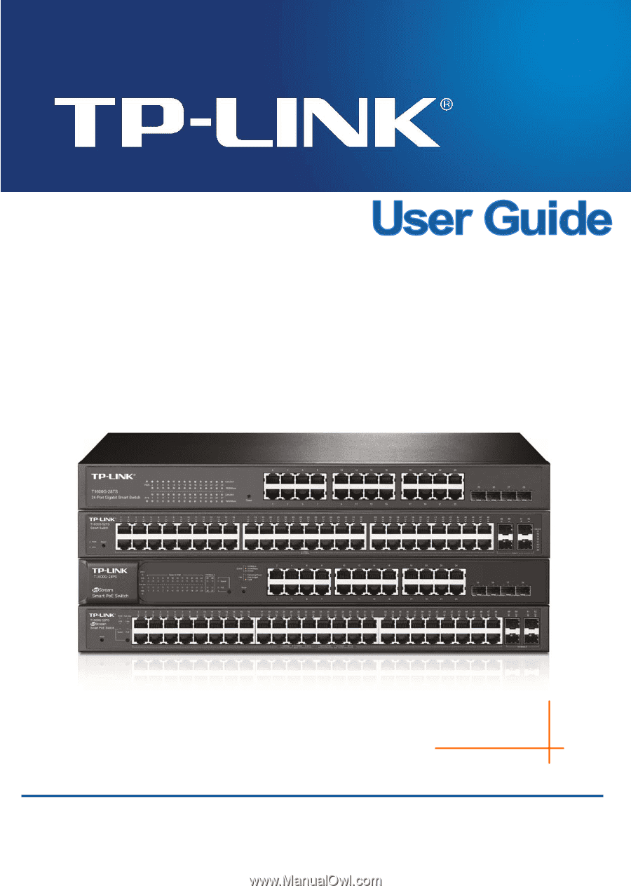
T1600G-28TS (TL-SG2424)
T1600G-52TS (TL-SG2452)
T1600G-28PS (TL-SG2424P)
T1600G-52PS (TL-SG2452P)
JetStream Gigabit Smart Switch
REV1.1.2
1910011399