TP-Link T3700G-52TQ T3700G-52TQUN V1 Installation Guide - Page 14
Installing & Removing the Power Supply Module
 |
View all TP-Link T3700G-52TQ manuals
Add to My Manuals
Save this manual to your list of manuals |
Page 14 highlights
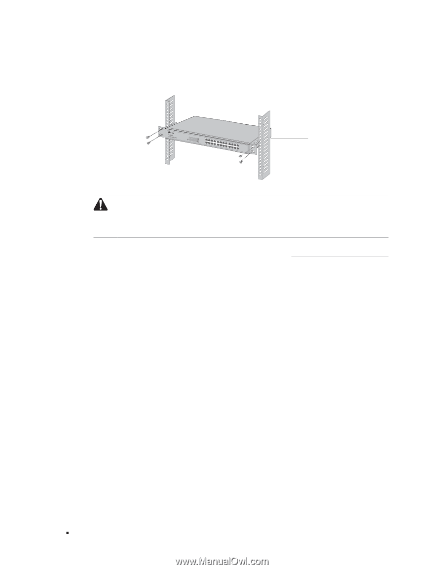
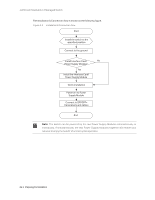
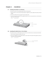
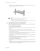
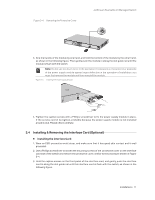
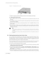
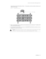
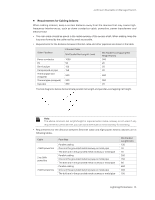
JetStream Stackable L3 Managed Switch 3. After the brackets are attached to the device, use suitable screws (not provided) to secure the brackets to the rack, as illustrated in the following figure. Figure 3-3 Rack Installation Rack Caution: ■■ Please set 5 to 10cm gaps around the device for air circulation. ■■ Please avoid any heavy thing placed on the device. ■■ Please mount devices in sequence from the bottom to top of the rack and ensure a certain clearance between devices for the purpose of heat dissipation. 3.3 Installing & Removing the Power Supply Module One Power Supply Module has already been installed in the switch. Operate as the following steps if you need to replace the Power Supply Module. ■■ Removing the Power Supply Module 1. Wear an ESD-preventive wrist strap, and make sure that it has good skin contact and is well grounded. 2. Remove the power cord from the power module and the external power supply system. 3. Use a Phillips screwdriver to loosen the captive screws at both sides of the power supply module until all spring pressure is released. 4. Pull the handle by one hand towards you along the guide rails, and hold the bottom of the module by the other hand, until it completely comes out of the switch chassis. 5. In order to better protect the removed power supply module, it is recommended to package it by an antistatic bag. 6. After removing the PSM150-AC, please install the protective cover as soon as possible to prevent dust from entering and ensure the normal ventilation in the switch. ■■ Installing the Power Supply Module 1. Wear an ESD-preventive wrist strap, and make sure that it has good skin contact and is well grounded. 2. If the protective cover has been installed on the power supply module slot of the switch, use a Phillips screwdriver to loosen the mounting screws of the protective cover and remove the protective cover, as shown in the following figure. 10 Installation
-
 1
1 -
2
-
3
-
4
-
5
-
6
-
7
-
8
-
 9
9 -
 10
10 -
 11
11 -
 12
12 -
 13
13 -
 14
14 -
 15
15 -
 16
16 -
 17
17 -
 18
18 -
 19
19 -
20
-
21
-
22
-
23
-
24
-
25
-
26
-
27
-
28
-
29
-
30
-
31
-
32
-
33
-
34
-
35
-
36
 |
 |