TP-Link TL-SG2452 TL-SG2452 V1 User Guide - Page 13
Rear Panel, Reset, 100/1000Mbps Ports, SFP Ports, Status, Indication, Grounding Terminal - switch
 |
View all TP-Link TL-SG2452 manuals
Add to My Manuals
Save this manual to your list of manuals |
Page 13 highlights
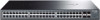
Reset: Press this button for five seconds or above to reset the software setting back to factory default setting. 10/100/1000Mbps Ports: Designed to connect to the device with a bandwidth of 10Mbps, 100Mbps or 1000Mbps. Each has a corresponding 1000Mbps LED. SFP Ports: Designed to install the SFP module. The TL-SG2452 features 4 individual SFP ports. Note: For TL-SG2452, the SFP port can only be used with a gigabit module. LEDs Name PWR SYS 10/100/ 1000Mbps Status Indication On Power is on. Flashing Power supply is abnormal. Off Power is off or power supply is abnormal. On The switch is working abnormally. Flashing The switch is working normally. Off Green On Flashing Yellow On Flashing The switch is working abnormally. A 1000Mbps device is connected to the corresponding port but no activity. Data is being transmitted or received. A 10/100Mbps device is connected to the corresponding port but no activity. Data is being transmitted or received. Off No device is connected to the corresponding port. 2.3.2 Rear Panel The rear panel of TL-SG2452 features a power socket and a Grounding Terminal (marked with ). Figure 2-2 Rear Panel of TL-SG2452 Grounding Terminal: TL-SG2452 already comes with Lightning Protection Mechanism. You can ground the switch through the PE (Protecting Earth) cable of AC cord or with Ground Cable. AC Power Socket: Connect the female connector of the power cord here, and the male connector to the AC power outlet. Please make sure the voltage of the power supply meets the requirement of the input voltage (100-240V~ 50/60Hz 1.0A). Return to CONTENTS 6
-
 1
1 -
2
-
3
-
4
-
5
-
6
-
7
-
 8
8 -
 9
9 -
 10
10 -
 11
11 -
 12
12 -
 13
13 -
 14
14 -
 15
15 -
 16
16 -
 17
17 -
 18
18 -
19
-
20
-
21
-
22
-
23
-
24
-
25
-
26
-
27
-
28
-
29
-
30
-
31
-
32
-
33
-
34
-
35
-
36
-
37
-
38
-
39
-
40
-
41
-
42
-
43
-
44
-
45
-
46
-
47
-
48
-
49
-
50
-
51
-
52
-
53
-
54
-
55
-
56
-
57
-
58
-
59
-
60
-
61
-
62
-
63
-
64
-
65
-
66
-
67
-
68
-
69
-
70
-
71
-
72
-
73
-
74
-
75
-
76
-
77
-
78
-
79
-
80
-
81
-
82
-
83
-
84
-
85
-
86
-
87
-
88
-
89
-
90
-
91
-
92
-
93
-
94
-
95
-
96
-
97
-
98
-
99
-
100
-
101
-
102
-
103
-
104
-
105
-
106
-
107
-
108
-
109
-
110
-
111
-
112
-
113
-
114
-
115
-
116
-
117
-
118
-
119
-
120
-
121
-
122
-
123
-
124
-
125
-
126
-
127
-
128
-
129
-
130
-
131
 |
 |
