TP-Link TL-SL2428 TL-SL2428 V1 IG 7106503901 - Page 7
Rear Panel
 |
View all TP-Link TL-SL2428 manuals
Add to My Manuals
Save this manual to your list of manuals |
Page 7 highlights
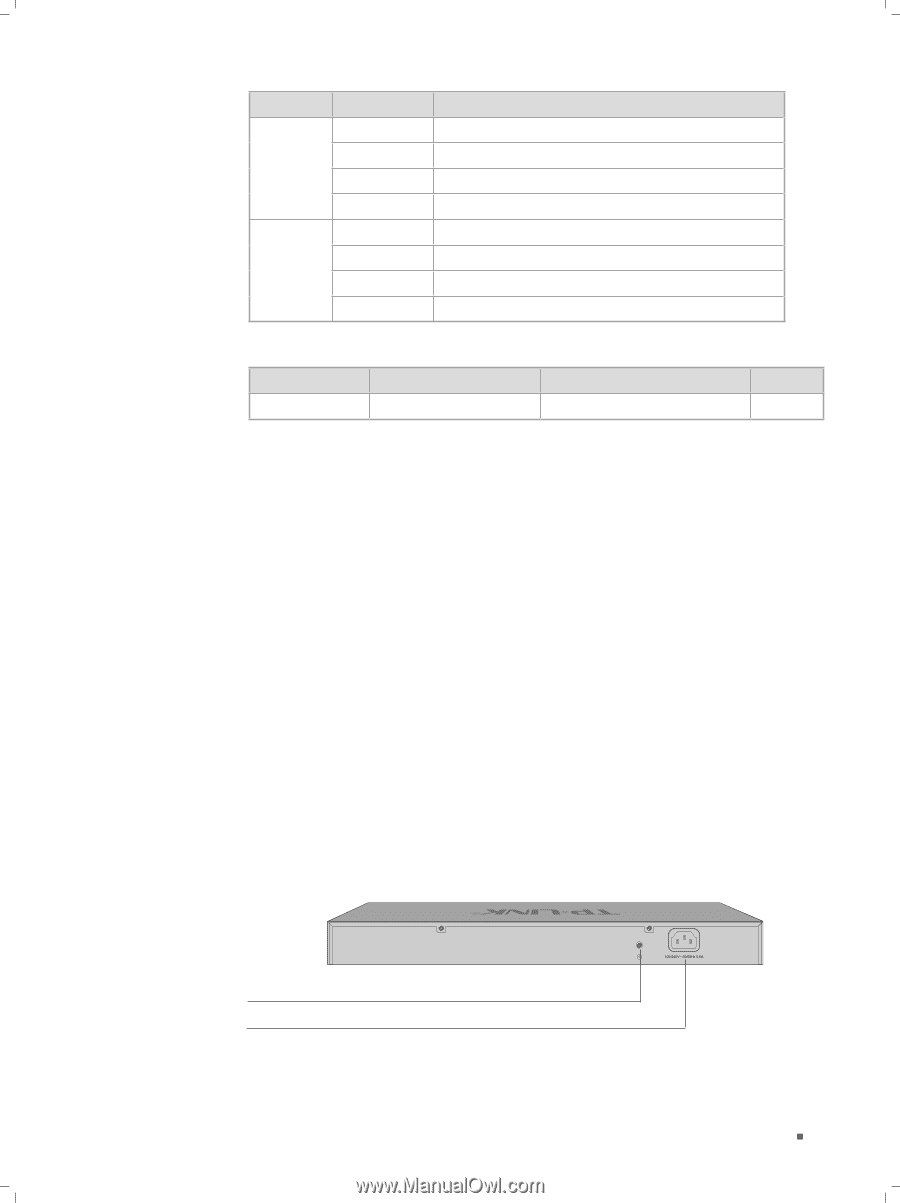
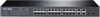
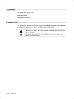
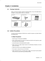
Smart Switch LED 10/100M 1000M Status On Flashing Green Yellow On Flashing Green Yellow Indication A device is linked to the corresponding port Data is being transmitted or received The linked device is running at 100Mbps The linked device is running at 10Mbps A device is linked to the corresponding port Data is being transmitted or received The linked device is running at 1000Mbps The linked device is running at 10/100Mbps Port Feature Model TL-SL2428 10/100Mbps RJ45 Port 10/100/1000Mbps RJ45 Port SFP Port 24 4 2 RESET With the Switch powered on, press Reset button for five seconds to reset the software setting to its factory default settings. 10/100Mbps RJ45 Port Designed to connect to the device with a bandwidth of 10Mbps or 100Mbps. Each has a corresponding 10/100M LED. 10/100/1000Mbps RJ45 Port Designed to connect to the device with a bandwidth of 10Mbps, 100Mbps or 1000Mbps. Each has a corresponding 1000M LED. SFP Port Designed to install the SFP module. It shares LEDs with 1000Mbps ports. When a 1000Mbps SFP module is inserted into the SFP port, On(green1 LED of 1000M means a device is linked to the port and Flashing(green1 LED of 1000M indicates data is being transmitted or received on the port. ■■ Rear Panel The rear panel of TL-SL2428 is shown as the following figure. Grounding Terminal Power Socket FFFFFFFFFFFFRear Panel of TL-SL2428 Introduction 02
-
 1
1 -
 2
2 -
 3
3 -
 4
4 -
 5
5 -
 6
6 -
 7
7 -
 8
8 -
 9
9 -
 10
10 -
 11
11 -
 12
12 -
13
-
14
-
15
-
16
-
17
-
18
-
19
-
20
-
21
-
22
-
23
-
24
-
25
-
26
-
27
-
28
 |
 |