Tecumseh Products TC300 Operator Manual - Page 10
VI. Stopping Your Engine and, Short-Term Storage, VII. Maintenance - engine page 2 of 3
 |
View all Tecumseh Products TC300 manuals
Add to My Manuals
Save this manual to your list of manuals |
Page 10 highlights
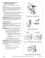
VI. Stopping Your Engine and Short-Term Storage Stop engine according to equipment manufacturer's instructions. WARNING To avoid unsupervised operation of an engine, especially by children, NEVER leave it unattended when it is running. Always turn off the engine after use and remove ignition key, if provided. 1. Move remote control on equipment, or any ignition stop switch on engine, to "STOP" or "OFF" (see equipment manufacturer's instructions). See Figure 15. 2. Close air vent screw on fuel fill cap, if present (see equipment manufacturer's instructions). See Figure 16. WARNING NEVER store the engine with fuel in the fuel tank inside a building with potential sources of ignition such as hot water and space heaters, clothes dryers, electric motors, etc. VII. Maintenance WARNING An adult should perform maintenance on this engine. Only allow children to perform maintenance if an adult has determined they are experienced and capable of such operation. WARNING To prevent accidental starting when working on equipment always: • Disconnect spark plug wire and keep it away from spark plug. See "G. Avoid Accidental Starts" instructions on page 2. See Figure 17. • Keep the disconnected spark plug wire securely away from metal parts where arcing could occur. • Attach the spark plug wire to the grounding post, if provided. • Disconnect battery at negative terminal first, if engine is equipped with an electric starter. CAUTION DO NOT start engine without pushing in yellow compression relief valve FIRST. Doing so may result in bruised fingers and accidental equipment movement which could result in minor or moderate injury. • Push yellow compression relief valve in. See Figure 18. • Turn off all engine switches. See Figure 15. • Remove ignition key, if provided. Figure 15. Switch in "OFF" Position I + Figure 16. Optional Air Vents Connected Disconnected Figure 17. Disconnecting/Connecting Spark Plug Page 8 Figure 18. Yellow Compression Relief Valve Two-Cycle Engine • Horizontal/Vertical Crankshaft • Air-Cooled 181-1277-14
-
 1
1 -
2
-
3
-
4
-
 5
5 -
 6
6 -
 7
7 -
 8
8 -
 9
9 -
 10
10 -
 11
11 -
 12
12 -
 13
13 -
 14
14 -
 15
15 -
16
-
17
-
18
-
19
-
20
-
21
-
22
-
23
-
24
 |
 |
