Thermador PODM301J Design Guide - Page 6
Planning Information - podmw301j
 |
View all Thermador PODM301J manuals
Add to My Manuals
Save this manual to your list of manuals |
Page 6 highlights
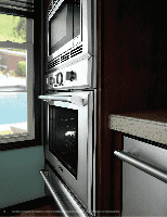
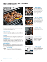
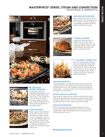
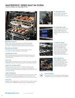
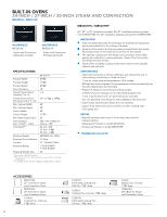
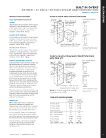
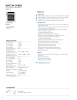
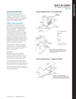
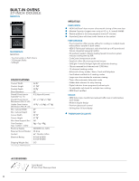
MODEL OPTIONS There are two Thermador Built-in Oven series to choose from - Professional and Masterpiece®. Each series features a distinctive style. Be sure to reference the correct model information in this design guide. INSTALLATION CONSIDERATIONS The information in this design guide provides key features, product dimensions, cutouts and installation specifications. Before installing a Thermador Oven, be sure to verify the cabinet dimensions and electrical connections. Also, always consult with the installation manual packed with the product for complete details before installing. Thermador Built-in Ovens may be placed in a wallmounted or under-counter installation. Thermador Single Ovens may also be installed below any Thermador Induction, Electric or Non-professional Gas Cooktop. When installing below a Thermador Induction Cooktop, a minimum 1" air gap must be maintained between the bottom of the cooktop and the top of the oven. An electric or non-professional Thermador Gas Cooktop can be installed above a Thermador Single Built-in Oven as long as there is no contact between the bottom of the cooktop and the top of the oven. Thermador Single Built-in Ovens are designed and approved for installation with Thermador Cooktops. Refer to the cooktop section for additional specifications. For oven support, install 2 x 4's extending front to back flush with the bottom and the side of the opening. The supporting base must be well secured to the floor/cabinet and level. When a Thermador Oven is installed at the end of a cabinet run, adjacent to a perpendicular wall or cabinet door, it is good practice to allow at least 1/4" space between the side of the oven and the wall or door. For ease of installation, some oven doors may be removed to reduce the weight of the oven by 30 lbs. per door, before installing into the cabinet. Refer to the installation manual for details. WARRANTY Limited warranty parts and labor (2 year) See page 308 for additional warranty details. ELECTRICAL LOCATION Refer to the appropriate installation diagram for details on conduit box location. 1.800.735.4328 | THERMADOR.COM BUILT-IN OVENS PLANNING INFORMATION ELECTRICAL SPECIFICATIONS Be sure your appliance is properly installed and grounded by a qualified technician. Installation, electrical connections and grounding must comply with all applicable local codes. All built-in ovens below are dual rated, designed to be connected to either 240/208V AC, 60 Hz, 4-wire, single-phase power supply. Install a suitable conduit box (not furnished). An appropriately-sized, UL-listed conduit connector must be used to correctly attach the conduit to the junction box. MODEL REQUIRED CIRCUIT BREAKER 240V, 60 Hz 208V, 60 Hz STEAM AND CONVECTION OVENS MES301HS 15 Amp 15 Amp MES301HP 15 Amp 15 Amp SINGLE OVENS ME301JS 30 Amp 30 Amp ME301JP 30 Amp 30 Amp MED271JS 30 Amp 30 Amp MED301JS 30 Amp 30 Amp MED301JP 30 Amp 30 Amp POD301J 30 Amp 30 Amp DOUBLE OVENS ME302JS 40 Amp 40 Amp ME302JP 40 Amp 40 Amp MED272JS 40 Amp 40 Amp MED302JS 40 Amp 40 Amp MED302JP 40 Amp 40 Amp PODC302J 40 Amp 40 Amp COMBINATION OVENS MEDMC301JS 50 Amp 50 Amp MEDMC301JP 50 Amp 50 Amp PODM301J 50 Amp 50 Amp TRIPLE COMBINATION OVENS MEDMCW71JS 50 Amp 50 Amp MEDMCW31JS 50 Amp 50 Amp MEDMCW31JP 50 Amp 50 Amp PODMW301J 50 Amp 50 Amp IMPORTANT Local Codes may vary; installation, electrical connections and grounding must comply with all applicable local codes. If local codes permit grounding through the electrical supply neutral, connect both the white neutral wire and the bare ground wire from the oven to the white neutral electrical supply wire. A 4-wire connection is preferred, but where local codes permit, a 3-wire connection is also acceptable. 75 BUILT-IN OVENS
-
 1
1 -
 2
2 -
 3
3 -
 4
4 -
 5
5 -
 6
6 -
 7
7 -
 8
8 -
 9
9 -
 10
10 -
 11
11 -
 12
12 -
13
-
14
-
15
-
16
-
17
-
18
-
19
-
20
-
21
-
22
-
23
-
24
-
25
-
26
 |
 |