Thermador PRG366GH Installation Instructions - Page 13
Step 5: Gas Requirements and, Hookup - 10
 |
View all Thermador PRG366GH manuals
Add to My Manuals
Save this manual to your list of manuals |
Page 13 highlights
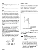
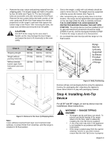
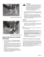
• Prepare holes at fastener locations as identified below: • For walls, wall studs, or floors composed of solid wood or metal, drill 1/8" pilot holes. • For walls or floors composed of drywall, sheet-rock or other soft materials, drill 3/16" holes to a minimum depth of 1-3/4", then tap plastic anchors into each of the holes using a hammer. • For walls or floors composed of concrete or concrete block, drill 3/16" holes to a minimum depth of 1-3/4", then tap concrete anchors into each of the holes using a hammer. • For walls or floors having ceramic tile covering, drill 3/16" holes through the tile only, then drill into the material behind the tile as indicated immediately above. • If the range is moved to a new location, the Anti-Tip Device must be removed and reinstalled. Mounting Anti-Tip Bracket The alternative floor mounted bracket shall be installed as follows: 1. Place bracket on floor in position shown in Figure 8 (Bracket may be used in either corner of the installation area). 2. Secure to floor or wall stud. 3. Later, when the unit is installed, the adjustable leg will slide under the bracket. Step 5: Gas Requirements and Hookup Verify the type of gas being used at the installation site. As shipped from the factory, units are configured for use with only natural gas or propane (LP) gas. Make certain the range matches the type of gas available at this location. These ranges are NOT convertible between different types of gas. Figure 8: Placement of Anti-Tip Bracket (Top View) For installation of the appliance at high altitude, please consult your local gas company for their recommendation of the correct orifice sizes and any other necessary adjustments that will provide proper gas combustion at specified altitudes. CAUTION When connecting unit to propane gas, make certain the propane gas tank is equipped with its own high pressure regulator in addition to the pressure regulator supplied with the appliance. The pressure of the gas supplied to the appliance regulator must not exceed 14" (34.9 mb) water column. Natural Gas Requirements: Inlet Connection: Supply Pressure: Manifold Pressure: 1/2" NPT internal (Minimum 3/4" dia. flex line.) 6" min. to 14" max. water column. (14.9 to 34.9 mb) 5" water column (12.5 mb) Propane Gas Requirements: Inlet Connection: Supply Pressure: 1/2" NPT internal (Minimum 3/4" dia. flex line.) 11" min. to 14"max. water column. (27.4 mb to 34.9 mb) Manifold Pressure: 10" water column (24.9 mb) WARNING Gas line must not come in contact with any components inside back cover of range. English 11
-
 1
1 -
2
-
3
-
4
-
5
-
6
-
7
-
 8
8 -
 9
9 -
 10
10 -
 11
11 -
 12
12 -
 13
13 -
 14
14 -
 15
15 -
 16
16 -
 17
17 -
 18
18 -
19
-
20
-
21
-
22
-
23
-
24
-
25
-
26
-
27
-
28
-
29
-
30
-
31
-
32
-
33
-
34
-
35
-
36
-
37
-
38
-
39
-
40
-
41
-
42
-
43
-
44
-
45
-
46
-
47
-
48
-
49
-
50
-
51
-
52
-
53
-
54
-
55
-
56
-
57
-
58
-
59
-
60
-
61
-
62
-
63
-
64
 |
 |
