Toshiba IK-1000 Instruction Manual - Page 8
Also used to perform ONE PUSH WB. - i camera
 |
UPC - 032017480407
View all Toshiba IK-1000 manuals
Add to My Manuals
Save this manual to your list of manuals |
Page 8 highlights
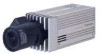
q DC IN 12V terminal w VIDEO terminal e RS232C terminal r DISP button t PAGE button y MENU UP button u MENU DOWN button i DATA UP (AWB) button o DATA DOWN button !0 S-VIDEO terminal !1 Camera Support Fitting !2 IRIS terminal (4P) !3 Image sensor Accepts a DC power unit (12 V). Outputs VBS signal. Connected to monitor, recording device, etc. (BNC connector) Used to control functions by communications via RS232C. Used when switching the display. Used when switching to the setting screen and when selecting the setting screens. Selecting the function to be confirmed or changed on the setting screen. Selecting the function to be confirmed or changed on the setting screen. Changes the setup contents of the function selected by the MENU (UP/DOWN) button. (Also used to perform ONE PUSH WB.) Changes the setup contents of the function selected by the MENU (UP/DOWN) button. Outputs Y (brightness signal) and C (color signal). Fitting to fix the camera to the housing. Connected when using automatic iris lens. Equipped with imaging element. Carefully prevent dust, dirt, fingerprint, etc. Cautions • Because the surface is coated, use a soft cloth when wiping. Using abrasives may strip the coating. - 8 -
-
 1
1 -
2
-
 3
3 -
 4
4 -
 5
5 -
 6
6 -
 7
7 -
 8
8 -
 9
9 -
 10
10 -
 11
11 -
 12
12 -
 13
13 -
14
-
15
-
16
-
17
-
18
-
19
-
20
-
21
-
22
-
23
-
24
-
25
-
26
-
27
-
28
-
29
-
30
-
31
-
32
-
33
-
34
-
35
-
36
-
37
-
38
-
39
-
40
 |
 |
