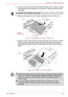
Toshiba Portege M750 PPM75A Users Manual AU/NZ - Page 84
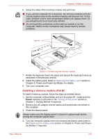
Replace the keyboard and secure it using the two screws.
 |
View all Toshiba Portege M750 PPM75A manuals
Add to My Manuals
Save this manual to your list of manuals |
Page 84 highlights
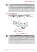
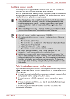
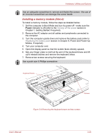
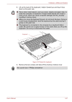
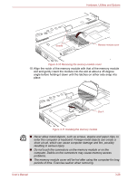
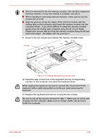
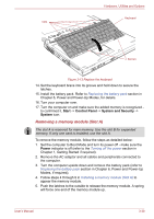
Hardware, Utilities and Options ■ Slot A is reserved for the first memory module. Use slot B for expansion memory modules. If only one module is installed, use slot A. ■ When inserting or removing memory modules, make sure to use the correct slot (A or B). ■ Align the grooves along the edges of the memory module with the locking tabs on the connector and insert the memory module into the connector firmly - if you find it difficult to install the memory module, gently prise the locking tabs outwards using the tip of your finger. Please also ensure that you hold the memory module along its left and right hand edges - the edges with the grooves in. 11. Screw in the two screws and replace the memory module cover. Screws Memory module cover Figure 3-12 Seating the memory module cover 12. Insert the tabs on the front of the keyboard into the corresponding notches on the computer and place the keyboard down. When seating the keyboard, be sure to connect the circuit board if the keyboard ribbon cable was pulled out while you were removing the keyboard. 13. Replace the keyboard and secure it using the two screws. Be sure to use all two screws removed in step 7. Make sure no screw was dropped into the computer. Make sure no foreign matter can be found inside the computer. User's Manual 3-29
-
 1
1 -
2
-
3
-
4
-
5
-
6
-
7
-
8
-
9
-
10
-
11
-
12
-
13
-
14
-
15
-
16
-
17
-
18
-
19
-
20
-
21
-
22
-
23
-
24
-
25
-
26
-
27
-
28
-
29
-
30
-
31
-
32
-
33
-
34
-
35
-
36
-
37
-
38
-
39
-
40
-
41
-
42
-
43
-
44
-
45
-
46
-
47
-
48
-
49
-
50
-
51
-
52
-
53
-
54
-
55
-
56
-
57
-
58
-
59
-
60
-
61
-
62
-
63
-
64
-
65
-
66
-
67
-
68
-
69
-
70
-
71
-
72
-
73
-
74
-
75
-
76
-
77
-
78
-
 79
79 -
 80
80 -
 81
81 -
 82
82 -
 83
83 -
 84
84 -
 85
85 -
 86
86 -
 87
87 -
 88
88 -
 89
89 -
90
-
91
-
92
-
93
-
94
-
95
-
96
-
97
-
98
-
99
-
100
-
101
-
102
-
103
-
104
-
105
-
106
-
107
-
108
-
109
-
110
-
111
-
112
-
113
-
114
-
115
-
116
-
117
-
118
-
119
-
120
-
121
-
122
-
123
-
124
-
125
-
126
-
127
-
128
-
129
-
130
-
131
-
132
-
133
-
134
-
135
-
136
-
137
-
138
-
139
-
140
-
141
-
142
-
143
-
144
-
145
-
146
-
147
-
148
-
149
-
150
-
151
-
152
-
153
-
154
-
155
-
156
-
157
-
158
-
159
-
160
-
161
-
162
-
163
-
164
-
165
-
166
-
167
-
168
-
169
-
170
-
171
-
172
-
173
-
174
-
175
-
176
-
177
-
178
-
179
-
180
-
181
-
182
-
183
-
184
-
185
-
186
-
187
-
188
-
189
-
190
-
191
-
192
-
193
-
194
-
195
-
196
-
197
-
198
-
199
-
200
-
201
-
202
-
203
-
204
-
205
-
206
-
207
-
208
-
209
-
210
-
211
-
212
-
213
-
214
-
215
-
216
-
217
-
218
-
219
-
220
-
221
-
222
-
223
-
224
-
225
-
226
-
227
-
228
-
229
-
230
-
231
-
232
-
233
-
234
-
235
-
236
-
237
-
238
-
239
-
240
-
241
-
242
-
243
-
244
-
245
-
246
-
247
-
248
-
249
-
250
-
251
-
252
-
253
-
254
-
255
-
256
-
257
-
258
-
259
-
260
-
261
-
262
-
263
-
264
-
265
-
266
-
267
-
268
-
269
 |
 |
