Toshiba Portege R100 Maintenance Manual - Page 45
Procedure 2, Error Code Check
 |
View all Toshiba Portege R100 manuals
Add to My Manuals
Save this manual to your list of manuals |
Page 45 highlights
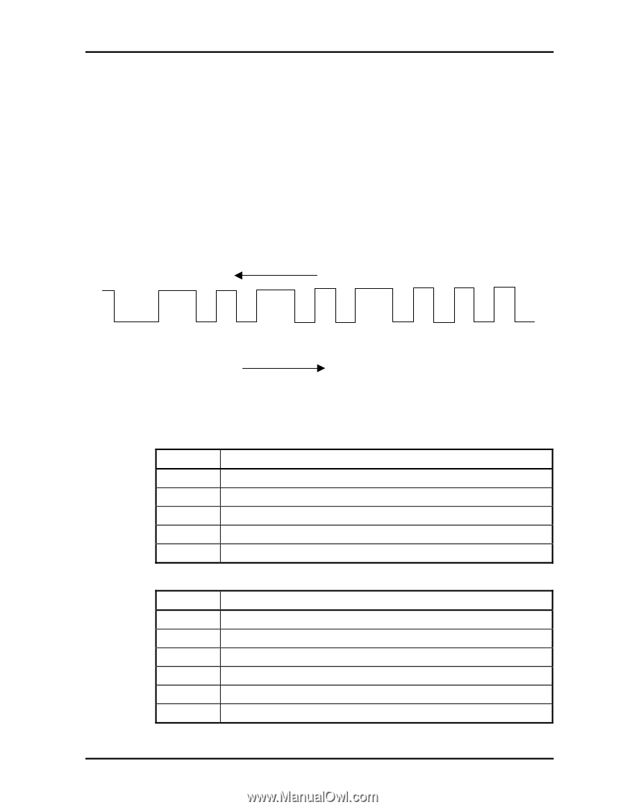
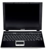
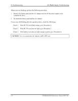
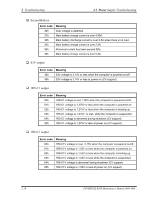
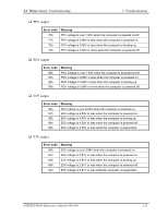
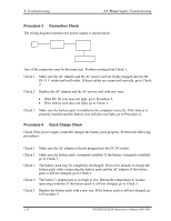
2.3 Power Supply Troubleshooting 2 Troubleshooting Procedure 2 Error Code Check If the power supply microprocessor detects a malfunction, the DC IN icon blinks orange. The blink pattern indicates an error as shown below. Start Error code (8 bit) "1" "0" Interval between data bits The error code begins with LSB (Least Significant bit) Example: Error code 11h (Error codes are given in hexadecimal format.) Off for 2 seconds On for one second On for half second On for half second Re ad On 1 0 0 0 1 0 0 0 Off Start D0 D1 D2 D3 D4 D5 D6 D7 Order Check 1 Convert the DC IN icon blink pattern into the hexadecimal error code and compare it to the tables below. Then go to Check 2. DC power supply (AC adapter) Error code Meaning 10h AC Adapter output voltage is over 16.5V. 11h Commondock output voltage is over 16.5V. 12h Current from the DC power supply is over 4.95A. 13h Current from the DC power supply is over 0.5A when there is no load. 14h Abnormal current has been sensed 0[A]. Main Battery Error code Meaning 20h Over voltage is detected. 21h Main battery charge current is over 4.95A. 22h Main battery discharge current is over 0.5A when there is no load. 23h Main battery charge current is over 2.3A. 24h Abnormal current has been sensed 0[A]. 25h Main battery charge current is over 0.3A. PORTEGE R100 Maintenance Manual (960-440) 2-9
-
 1
1 -
2
-
3
-
4
-
5
-
6
-
7
-
8
-
9
-
10
-
11
-
12
-
13
-
14
-
15
-
16
-
17
-
18
-
19
-
20
-
21
-
22
-
23
-
24
-
25
-
26
-
27
-
28
-
29
-
30
-
31
-
32
-
33
-
34
-
35
-
36
-
37
-
38
-
39
-
 40
40 -
 41
41 -
 42
42 -
 43
43 -
 44
44 -
 45
45 -
 46
46 -
 47
47 -
 48
48 -
 49
49 -
 50
50 -
51
-
52
-
53
-
54
-
55
-
56
-
57
-
58
-
59
-
60
-
61
-
62
-
63
-
64
-
65
-
66
-
67
-
68
-
69
-
70
-
71
-
72
-
73
-
74
-
75
-
76
-
77
-
78
-
79
-
80
-
81
-
82
-
83
-
84
-
85
-
86
-
87
-
88
-
89
-
90
-
91
-
92
-
93
-
94
-
95
-
96
-
97
-
98
-
99
-
100
-
101
-
102
-
103
-
104
-
105
-
106
-
107
-
108
-
109
-
110
-
111
-
112
-
113
-
114
-
115
-
116
-
117
-
118
-
119
-
120
-
121
-
122
-
123
-
124
-
125
-
126
-
127
-
128
-
129
-
130
-
131
-
132
-
133
-
134
-
135
-
136
-
137
-
138
-
139
-
140
-
141
-
142
-
143
-
144
-
145
-
146
-
147
-
148
-
149
-
150
-
151
-
152
-
153
-
154
-
155
-
156
-
157
-
158
-
159
-
160
-
161
-
162
-
163
-
164
-
165
-
166
-
167
-
168
-
169
-
170
-
171
-
172
-
173
-
174
-
175
-
176
-
177
-
178
-
179
-
180
-
181
-
182
-
183
-
184
-
185
-
186
-
187
-
188
-
189
-
190
-
191
-
192
-
193
-
194
-
195
-
196
-
197
-
198
-
199
-
200
-
201
-
202
-
203
-
204
-
205
-
206
-
207
-
208
-
209
-
210
-
211
-
212
-
213
-
214
-
215
-
216
-
217
-
218
-
219
-
220
-
221
-
222
-
223
-
224
-
225
-
226
-
227
-
228
-
229
-
230
-
231
-
232
-
233
-
234
-
235
-
236
-
237
-
238
-
239
-
240
-
241
-
242
-
243
-
244
-
245
-
246
-
247
-
248
-
249
-
250
-
251
-
252
-
253
-
254
-
255
-
256
-
257
-
258
-
259
-
260
-
261
-
262
-
263
-
264
-
265
-
266
-
267
-
268
-
269
-
270
-
271
-
272
-
273
-
274
-
275
-
276
-
277
-
278
-
279
-
280
-
281
-
282
-
283
-
284
-
285
-
286
-
287
-
288
-
289
-
290
-
291
-
292
 |
 |