Toshiba RS-TX20 User Manual - Page 25
Audio/Video Output, RF Out, Cable/Antenna-RF In, Channel changing cables, IR Control cable for one box
 |
View all Toshiba RS-TX20 manuals
Add to My Manuals
Save this manual to your list of manuals |
Page 25 highlights
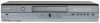
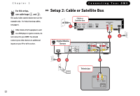
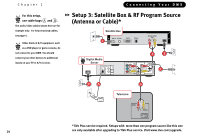
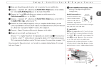
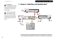
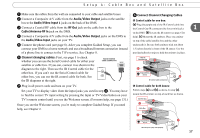
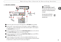
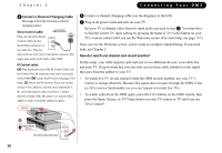
Setup 4: Cable Box and Satellite Box ᕡ Make sure the cables from the wall are connected to your cable and satellite boxes. ᕢ Connect a Composite A/V cable from the Audio/Video Output jacks on the satellite box to the Audio/Video Input 1 jacks on the back of the DMS. ᕣ Connect a Coaxial RF cable from the RF Out jack on the cable box to the Cable/Antenna-RF In jack on the DMS. ᕤ Connect a Composite A/V cable from the Audio/Video Output jacks on the DMS to the Audio/Video Input jacks on your TV. ᕥ Connect the phone cord (see page 8). After you complete Guided Setup, you can connect your DMS to a home network and use a broadband Internet connection instead of a phone line to connect to the TiVo service. See Chapter 8. ᕦ Channel changing cables: First, see page 5 to check whether you can use the Serial Control cable for either your satellite or cable box. If you can, connect it as shown in the Serial Control cable connection Serial diagram to the right. Then use the IR Control cable for the other box. If you can't use the Serial Control cable for either box, you can use the IR control cable for both. See the IR diagrams at the right. ᕧ Plug in all power cords and turn on your TV. Set your TV to display video from the input jacks you used in step ᕤ. You may have to find the correct TV input setting by pressing the Input or TV/Video button on your TV's remote control until you see the Welcome screen. (For more help, see page 131.) Once you see the Welcome screen, you're ready to complete Guided Setup. If you need help, see Chapter 2. ᕦ Connect Channel Changing Cables IR Control cable for one box: (a) Plug the purple end of the IR Control cable into the Control Out-IR connector (the lower mini-jack) 1 on the DMS. (b) Locate the IR sensor (see page 6 for help). (c) Mount the IR emitters. Place one emitter on top of the cable/satellite box and the other underneath it. Be sure both emitters stick out about 1.5 inches directly in front of the IR sensor. Use the provided adhesive strips to hold the emitters in place. Cable or Satellite Box c b Digital Media Server ® a IR Control cable connection IR Control cable for both boxes: Follow steps (a) and (b) as above. In step (c), mount the IR emitters on top of each box as shown. Satellite Box c b Cable Box c b Digital Media Server ® IR Control for Cable and Satellite a 17
-
 1
1 -
2
-
3
-
4
-
5
-
6
-
7
-
8
-
9
-
10
-
11
-
12
-
13
-
14
-
15
-
16
-
17
-
18
-
19
-
 20
20 -
 21
21 -
 22
22 -
 23
23 -
 24
24 -
 25
25 -
 26
26 -
 27
27 -
 28
28 -
 29
29 -
 30
30 -
31
-
32
-
33
-
34
-
35
-
36
-
37
-
38
-
39
-
40
-
41
-
42
-
43
-
44
-
45
-
46
-
47
-
48
-
49
-
50
-
51
-
52
-
53
-
54
-
55
-
56
-
57
-
58
-
59
-
60
-
61
-
62
-
63
-
64
-
65
-
66
-
67
-
68
-
69
-
70
-
71
-
72
-
73
-
74
-
75
-
76
-
77
-
78
-
79
-
80
-
81
-
82
-
83
-
84
-
85
-
86
-
87
-
88
-
89
-
90
-
91
-
92
-
93
-
94
-
95
-
96
-
97
-
98
-
99
-
100
-
101
-
102
-
103
-
104
-
105
-
106
-
107
-
108
-
109
-
110
-
111
-
112
-
113
-
114
-
115
-
116
-
117
-
118
-
119
-
120
-
121
-
122
-
123
-
124
-
125
-
126
-
127
-
128
-
129
-
130
-
131
-
132
-
133
-
134
-
135
-
136
-
137
-
138
-
139
-
140
-
141
-
142
-
143
-
144
-
145
-
146
-
147
-
148
-
149
-
150
-
151
-
152
-
153
-
154
-
155
-
156
-
157
-
158
-
159
-
160
-
161
-
162
-
163
-
164
-
165
-
166
-
167
-
168
-
169
-
170
-
171
-
172
-
173
-
174
-
175
-
176
-
177
-
178
-
179
-
180
-
181
-
182
-
183
-
184
-
185
-
186
-
187
-
188
-
189
-
190
-
191
-
192
-
193
-
194
-
195
-
196
-
197
-
198
-
199
-
200
-
201
-
202
-
203
-
204
 |
 |