Toshiba Satellite Pro 4600 Replacement Instructions - Page 10
Toshiba Satellite Pro 4600 Manual
 |
View all Toshiba Satellite Pro 4600 manuals
Add to My Manuals
Save this manual to your list of manuals |
Page 10 highlights
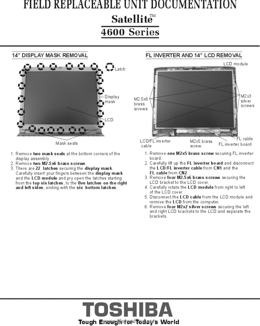
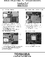
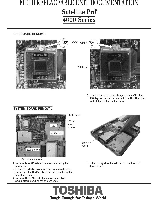
FIELD REPLACEABLE UNIT DOCUMENTATION Satellite' 4600 Series 14.' DISPLAY MASK REMOVAL YL 0 - 0 ()Latch FL INVERTER AND 14" LCD REMOVAL LCD module Display I .. bras. al 1 Remove Iwo mask seals at the bottom corners of the display assembly 2 Remove Iwo M25. brass screws 3Thep ate 22 latch. securing the display mask fatefully inset, put fingets between Pe display mask and Me L. moduK a. pty open the latches staffing from the fop six fetches,. Me flve latches en the right and left sides, ending with the els bottom latches LCDF inveite cable 2,1 FL cable FL inverter board 1. ibE :re one M2a5 brass screw securing FL inverter 2.0 refully lift the FL inverter board and disconnect the LC0IFL kwerter cable from Cf11 a. the F cable from Cf12 3 emove.ur M2.54 brass screws securing the L bracket to the LCD cover 4. Carefully rohte the LCD module from right to left of the LC0 cover. 5 0 sconnecithe LCD cable from the LCD module and move the LCD from the computer 6. Remove four bl2s2 silver screws securing the left .dcr:,g: LCD brackets. the LCD a. separate the TOSHIBA Tough Enough for Today's World
-
 1
1 -
2
-
3
-
4
-
 5
5 -
 6
6 -
 7
7 -
 8
8 -
 9
9 -
 10
10 -
 11
11
 |
 |