Toshiba TLP-XC2000U Owners Manual - Page 10
Names of the terminals on the rear panel, Names of each part on the document camara
 |
View all Toshiba TLP-XC2000U manuals
Add to My Manuals
Save this manual to your list of manuals |
Page 10 highlights
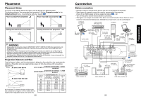
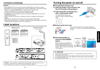
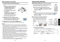
Preparations Names of the terminals on the rear panel (1) (2) (3) (4) (6) (8) (9) (5) (7) Name : Main Function (1) CONTROL terminal (2) AUDIO (L/R) terminal (3) VIDEO terminal (4) S-VIDEO terminal (5) AUDIO IN terminal (6) COMPUTER 1 IN terminal (7) AUDIO OUT terminal (8) COMPUTER 2 IN terminal (Also used for MONITOR OUT terminal) (9) Switch : When operating the projector via a computer, connect this to the controlling computer's RS-232C port. p.59 : Input audio signals from video equipment. : Input video signals from video equipment. : Input S video signals from video equipment. : Input audio signals from a computer, or from video equipment with a component video signal output terminal. : Input RGB signal from a computer or other source or a component video signal (Y/PB/PR) from video equipment. : Outputs audio signals. : Inputs RGB signal from a computer or other source or a component video signal (Y/PB/PR) rom video equipment. It can also be used as MONITOR OUT terminal by the switch of (9). : Switches between COMPUTER 2 IN and MONITOR OUT. COMPUTER 2 IN (Y/PB/PR 2) /MONITOR OUT Names of each part on the document camara (models with a document camera) (1) (2) (3) (4) (9) (6) (10) (7) (11) (8) (8) (5) Name : Main Function Camera (1) LED illumination (2) Focus ring (3) Camera lens (4) Camera arm (5) Infrared remote sensor : The illumination LED for referring documents. p.46 : Adjusts the focus. p.47 : The camera lens of the document camera. : Adjusts the camera angle. p.45 : Senses commands from the remote control. Control Panel (6) 50/60 Hz switch : Matches the shutter speed of the camera to your power system frequency. p.47 (7) CAMERA button : Switches between the camera input and the previous input. p.46 (8) CAMERA GAIN button : Adjusts the camera gain. p.47 (9) LOCK (W.BALANCE) indicator : Lights when the white balance has been locked. p.48 (10) W.BALANCE button : Switches between auto and locking of white balance. p.48 (11) LED LIGHT button : Switches on/off the LED illumination. p.46 18 19
-
 1
1 -
2
-
3
-
4
-
 5
5 -
 6
6 -
 7
7 -
 8
8 -
 9
9 -
 10
10 -
 11
11 -
 12
12 -
 13
13 -
 14
14 -
 15
15 -
16
-
17
-
18
-
19
-
20
-
21
-
22
-
23
-
24
-
25
-
26
-
27
-
28
-
29
-
30
-
31
 |
 |
